Driving tip device for rotating target

A technology of rotating target and tip, applied in the field of driving tip device for rotating target, can solve the problems of increasing production cost, being unable to adapt to different types of targets, affecting use, etc., reducing disassembly and assembly steps, and facilitating smooth work. Effect

Inactive Publication Date: 2011-12-07
黄峰
View PDF4 Cites 3 Cited by
  • Summary
  • Abstract
  • Description
  • Claims
  • Application Information

AI Technical Summary

Problems solved by technology

[0003] However, the structure of the drive end of the existing equipment is complex, which often leads to gaps in the connection when the target needs to be replaced, which affects subsequent use
Moreover, the drive end of the existing equipment is fixed and cannot be adjusted by rotation, and cannot adapt to different types of targets, which increases the production cost

Method used


Image

  • Driving tip device for rotating target
  • Driving tip device for rotating target

Examples


Embodiment Construction

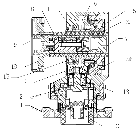
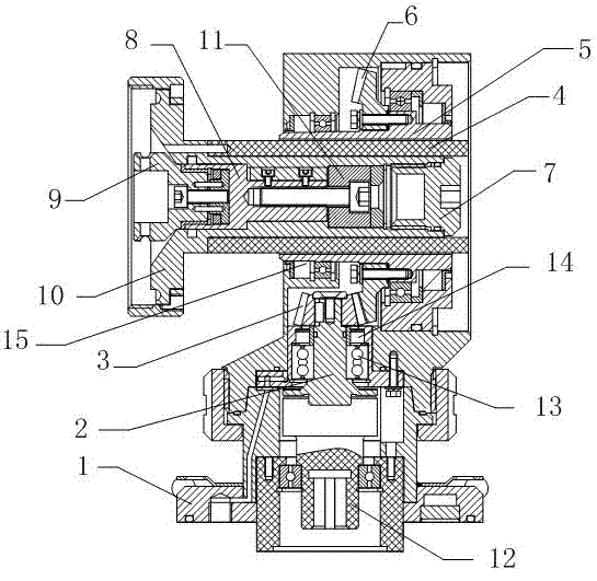
[0015] Such as figure 1 The driving end device for the rotating target shown includes a base 1, which is different in that: a cross shaft 2 is installed on the base 1 used in the present invention, and a pinion 3 is arranged on the top of the cross shaft 2 . Moreover, in order to improve the smooth operation of the pinion 3, an adapter sleeve 4 is connected to the driving end of the pinion gear 3. A hexagonal sleeve 5 is arranged on the periphery of the adapter sleeve 4, and a large gear 6 is installed on the hexagonal sleeve 5. Moreover, a driving assembly is arranged in the adapter sleeve 4 .

[0016] In view of a preferred embodiment of the present invention, in order to facilitate the correct transfer of driving operation, the drive assembly adopted in the present invention includes a head nut 7 , and a transition shaft 8 is provided at the top of the head nut 7 . At the same time, a shaft head 9 is arranged on the top of the transition shaft 8 , and a hexagonal main sha...


PUM


Abstract

The invention relates to a driving tip device for rotating a target. The driving tip device comprises a substrate, and is characterized in that: the substrate is provided with a cross shaft; the top of the cross shaft is provided with a pinion; a driving end of the pinion is connected with a reducing sleeve; a hexagonal sleeve is arranged at the periphery of the reducing sleeve, and is provided with a gearwheel; and a driving component is arranged in the reducing sleeve. Therefore, when the target is replaced, disassembly steps can be effectively reduced. Most importantly, the cross shaft is matched with the reducing sleeve, so that the driving rotary force can be effectively transferred and the target is facilitated to work smoothly.

Description

technical field [0001] The invention relates to a driving head device, in particular to a driving head device for a rotating target. Background technique [0002] At present, most of the equipment for producing coated glass adopts planar sputtering cathode target. Its working principle is: the glass to be coated is sent into the vacuum coating chamber, and a certain amount of high-purity process gas such as oxygen, nitrogen or Argon gas, under the action of electromagnetic field and free electrons, the process gas forms positively charged plasma. Under the attraction of the cathode carrying high negative voltage, the plasma bombards the fixed installation according to a certain trajectory and intensity under the control of the magnetic field. The coating material on the planar cathode target in the vacuum coating chamber is collided by gas molecules and deposited on the glass in a certain direction to form a film with a certain thickness. [0003] However, the structure of ...

Claims


Application Information

Patent Timeline
Patent Type & Authority Applications(China)
IPC IPC(8): C23C14/34
Inventor 黄峰
Owner 黄峰
Why Eureka
Try Eureka