A kind of color filter and its manufacturing method

A technology for color filters and manufacturing methods, which are applied in the fields of filters, optics, opto-mechanical equipment, etc., can solve the problems of low efficiency, many equipment, and complicated processes.

Active Publication Date: 2011-12-07
SHENZHEN CHINA STAR OPTOELECTRONICS TECH CO LTD
View PDF3 Cites 33 Cited by
  • Summary
  • Abstract
  • Description
  • Claims
  • Application Information

AI Technical Summary

Problems solved by technology

However, the manufacturing process of the color filter is complex, with many proce

Method used


Image

  • A kind of color filter and its manufacturing method
  • A kind of color filter and its manufacturing method
  • A kind of color filter and its manufacturing method

Examples


Embodiment Construction

[0049] It should be understood that the specific embodiments described here are only used to explain the present invention, and are not intended to limit the present invention.

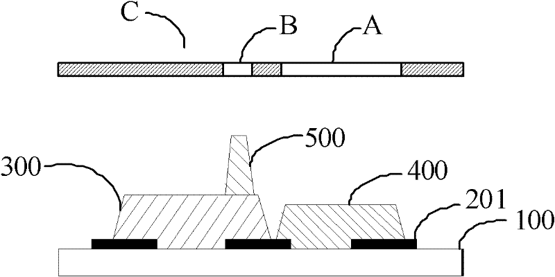
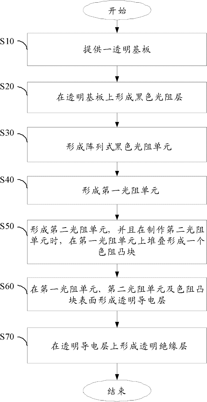
[0050] The invention proposes a manufacturing method of a color filter, the color filter includes a first photoresist unit and a second photoresist unit, the first photoresist unit and the second photoresist unit are color photoresist, and they are respectively used as A sub-pixel constitutes a pixel unit, and several pixel units arranged in an array form a pixel layer used on a color filter of a liquid crystal display. The manufacturing method of the color filter mainly includes the following steps:

[0051] After the first photoresist unit is formed, a photo spacer for controlling the gap between the array substrate and the color filter substrate is also formed when the second photoresist unit is manufactured. In addition to the first photoresist unit and the second photoresist unit, the color filt...


PUM


Abstract

The invention provides a color optical filter and a manufacturing method thereof. The color optical filter comprises a first photoresistance unit and a second photoresistance unit, wherein the first photoresistance unit and the second photoresistance unit constitute a pixel layer; and the manufacturing method comprises the following steps: forming the photoresistance unit and then forming a colorresistance convex block for controlling a gap between an array baseplate and a color film baseplate while manufacturing the second photoresistance unit. By adopting the manufacturing method, the manufacturing process can be reduced and the manufacturing cost of a liquid crystal display can be effectively reduced.

Description

technical field [0001] The invention relates to a manufacturing method of a color filter, in particular to a color filter provided with color-resisting bumps in a liquid crystal display and a manufacturing method thereof. Background technique [0002] In the traditional manufacturing process of color filters, when arranging spacers, generally a color-resist area in the photoresist unit area is selected, and a spacer layer of a single height is arranged to form liquid crystal perfusion gaps. However, because the height of the gap sublayer is single, and the surface height of the TFT (Thin Film Transistor, Thin Film Field Effect Transistor) layer bonded to the color filter is usually uneven, so the color filter is bonded to the TFT layer. In the bonding area with different heights, the rotation and recovery time of the liquid crystal will be different, causing display problems. [0003] In view of this, in the current improved gap sub-process, on the basis of the original gap...

Claims


Application Information

Patent Timeline
IPC IPC(8): G02B5/20G02F1/1335G03F7/00
CPCG03F7/00G02F1/1335G02F1/13394G02B5/20G02F1/133516
Inventor 伍浚铭
Owner SHENZHEN CHINA STAR OPTOELECTRONICS TECH CO LTD
Why Eureka
Try Eureka