
A thermal plasma arc flame generator

A thermal plasma and plasma technology, applied in the field of plasma, can solve the problems of low energy utilization rate, difficult ignition of the device, poor working stability, etc., and achieve the effects of improving working stability, large range and long length

Inactive Publication Date: 2011-12-07
四川金虹等离子技术有限公司
View PDF9 Cites 2 Cited by
  • Summary
  • Abstract
  • Description
  • Claims
  • Application Information

AI Technical Summary

Problems solved by technology

[0011] Aiming at the problems existing in the existing high-frequency induction thermal plasma generator, the present invention proposes a new thermal plasma arc flame generator, which can well solve the difficulty of ignition and poor working stability of the high-frequency induction thermal plasma generator , low power and low energy utilization

Method used


Image

  • A thermal plasma arc flame generator
  • A thermal plasma arc flame generator
  • A thermal plasma arc flame generator

Examples


Embodiment Construction

[0024] The present invention is described in detail below in conjunction with accompanying drawing:

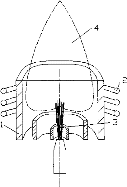
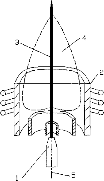
[0025] image 3 It is a schematic diagram of the principle of the present invention, and the thermal plasma arc flame generator of the present invention includes a high-frequency induction thermal plasma generator [2] and a laminar arc thermal plasma generator [1]. The central axis [5] of the laminar arc thermal plasma jet [3] and the high-frequency induction thermal plasma generator [2] coincides to guide the arc. The invention solves the problems of difficult ignition, cumbersome steps and easy arc breaking of the high-frequency induction thermal plasma generator, and greatly improves the working stability of the high-frequency induction thermal plasma generator. The laminar arc thermal plasma jet [3] is injected along the direction of the central axis [5] of the high frequency induction thermal plasma generator [2], and what is injected is the conductive arc plasma, which ...


PUM


Abstract

The invention belongs to the technical field of high-frequency induction thermal plasma. Aiming at the problems existing in current high-frequency induction thermal plasma generation devices, such as difficulty in ignition, poor working stability, high arc maintenance power, and low efficiency, the invention provides a thermal plasma arc flame generator. The present invention includes a laminar arc thermal plasma generator [1] and a high-frequency induction thermal plasma generator [2], which is characterized in that it is injected along the central axis [5] of the high-frequency induction thermal plasma generator [2] The laminar arc thermal plasma jet [3] plays the role of arc guidance, arc maintenance and induction enhancement of the high-frequency induction thermal plasma flame [4]. The laminar arc thermal plasma jet [3] has the advantages of long jet length, small fluctuation of flow field parameters, almost no entrainment of ambient gas, long length of high temperature zone, and small axial gradient of parameters such as temperature. Adopting the technical scheme of the present invention can solve the problems of difficult ignition and easy arc breaking of the high-frequency induction thermal plasma generator, reduce the operating frequency and arc maintenance power of the high-frequency induction thermal plasma generator, and increase the Efficiency facilitates the development of higher power high-frequency induction thermal plasma generators.

Description

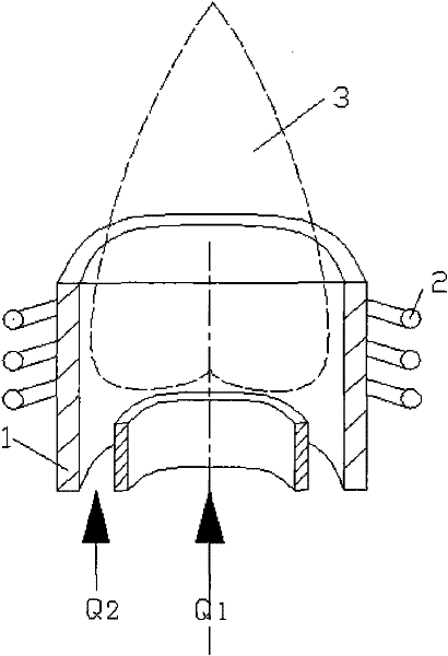
Technical field: [0001] The technology involved in the invention is electric arc and high-frequency induction thermal plasma technology, in particular to a high-frequency induction thermal plasma generator which introduces a laminar arc thermal plasma jet. Background technique: [0002] Since the high-frequency induction thermal plasma generation device was successfully developed, it has made considerable progress in the preparation of high-tech ceramic powder, ICP (inductively coupled plasma) spectrum analysis, spraying, superconductor, diamond film, diamond powder preparation, etc. for widespread use. [0003] At present, there are two main working modes of common high-frequency induction plasma generators: [0004] one is as figure 1 The generator device without pilot arc shown: a coil [2] wound with metal (such as copper tube) is placed outside the quartz tube [1], so that the high-frequency current supplied by the external power supply passes through the magnetic fiel...

Claims


Application Information

Patent Timeline
IPC IPC(8): H05H1/32
Inventor 朱华马再敏袁洁
Owner 四川金虹等离子技术有限公司
Learn More