

Non-impact self-adaptive trigger ignition device utilizing laminar flow plasma system
A laminar plasma and ignition device technology, which is applied in the ignition, plasma, combustion ignition and other directions using electric sparks, can solve the problems of high cost, low monomer power, low thermal efficiency, etc., and achieves good uniformity and fast heating speed. , the effect of uniform heat distribution
- Summary
- Abstract
- Description
- Claims
- Application Information
AI Technical Summary
Problems solved by technology
Method used
Image

Examples
Embodiment 1
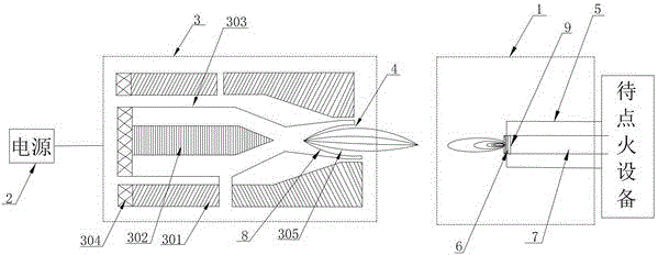
[0029] A non-impact self-adaptive trigger ignition device using a laminar flow plasma system, comprising a laminar flow plasma system and an ignition nozzle 1. The laminar flow plasma system includes a power source 2, a laminar flow plasma generator 3 and a nozzle 4, and the power source 2 is connected to the layer Flow plasma generator 3, nozzle 4 and laminar flow plasma generator 3 are detachably connected; the ignition nozzle 1 is arranged on the equipment to be ignited, and the ignition nozzle 1 includes a housing 5, an ignition electrode 6 and a conduit 7, and the ignition electrode 6 is arranged at the front end of the pipe 7 and the pipe 7 extends into the equipment to be ignited. The housing 5 is arranged on the outside of the ignition electrode 6 and the pipe 7; the nozzle 4 coincides with the central axis of the ignition nozzle 1.
Embodiment 2
[0031] A non-impact self-adaptive trigger ignition device using a laminar flow plasma system, comprising a laminar flow plasma system and an ignition nozzle 1. The laminar flow plasma system includes a power source 2, a laminar flow plasma generator 3 and a nozzle 4, and the power source 2 is connected to the layer Flow plasma generator 3, nozzle 4 and laminar flow plasma generator 3 are detachably connected; the ignition nozzle 1 is arranged on the equipment to be ignited, and the ignition nozzle 1 includes a housing 5, an ignition electrode 6 and a conduit 7, and the ignition electrode 6 is arranged at the front end of the pipe 7 and the pipe 7 extends into the equipment to be ignited. The housing 5 is arranged on the outside of the ignition electrode 6 and the pipe 7; the nozzle 4 coincides with the central axis of the ignition nozzle 1.
[0032] The laminar flow plasma generator 3 includes an anode structure 301, a cathode structure 302, and a multi-film cooling device 303. Th...
Embodiment 3
[0034] A non-impact self-adaptive trigger ignition device using a laminar flow plasma system, comprising a laminar flow plasma system and an ignition nozzle 1. The laminar flow plasma system includes a power source 2, a laminar flow plasma generator 3 and a nozzle 4, and the power source 2 is connected to the layer The jet plasma generator 3, the nozzle 4 and the laminar plasma generator 3 are detachably connected; the ignition nozzle 1 is arranged on the equipment to be ignited, and the ignition nozzle 1 includes a housing 5, an ignition electrode 6 and a conduit 7, and the ignition electrode 6 is arranged at the front end of the pipe 7 and the pipe 7 extends into the equipment to be ignited. The housing 5 is arranged on the outside of the ignition electrode 6 and the pipe 7; the nozzle 4 coincides with the central axis of the ignition nozzle 1.
[0035] The laminar flow plasma generator 3 includes an anode structure 301, a cathode structure 302, and a multi-film cooling device 3...
PUM
 Abstract
Description
Claims
Application Information