Dynamic Probe Detection System

A detection system, probe technology, used in the field of probe microscopy to solve problems such as accuracy or speed limitations

Active Publication Date: 2011-12-07
INFINITESIMA
View PDF15 Cites 13 Cited by
  • Summary
  • Abstract
  • Description
  • Claims
  • Application Information

AI Technical Summary

Problems solved by technology

However, to date, AFM imaging systems using oscillating probes have been limited in the accuracy or speed of image collection by the requirements of the feedback system.

Method used


Image

  • Dynamic Probe Detection System
  • Dynamic Probe Detection System
  • Dynamic Probe Detection System

Examples


Embodiment Construction

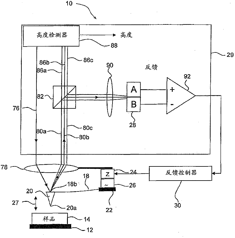
[0062] refer to figure 1 , schematically shows a modified implementation of an AFM generally indicated at 10 according to the invention. The AFM apparatus shown includes a movable platform 12 adapted to receive a sample 14 whose surface is to be viewed by a probe 16 . The probe 16 includes a cantilever beam 18 and a tip 20 that tapers to a point 20 a and is positioned toward one end of the cantilever beam 18 . The other end of the cantilever beam 18 is supported by a base plate 22 .

[0063] One or more drive motors (24, not shown) are used to drive sample 14 (together with stage 12) and / or probe 16 so that they can scan x, y and z directions relative to each other in three dimensions as described below. As is conventional in the art, the z-axis of the Cartesian coordinate system is taken to be the axis perpendicular to the plane occupied by the sample 14 . That is, the strength of the interaction force between the probe 16 and the sample 14 depends both on the xy position ...


PUM


Abstract

A dynamic probe detection system (29,32) is for use with a scanning probe microscope of the type that includes a probe (18) that is moved repeatedly towards and away from a sample surface. As a sample surface is scanned, an interferometer (88) generates an output height signal indicative of a path difference between light reflected from the probe (80a,80b,80c) and a height reference beam. Signal processing apparatus monitors the height signal and derives a measurement for each oscillation cycle that is indicative of the height of the probe. This enables extraction of a measurement that represents the height of the sample, without recourse to averaging or filtering, that may be used to form an image of the sample. The detection system may also include a feedback mechanism that is operable to maintain the average value of a feedback parameter at a set level.

Description

technical field [0001] The present invention relates to the field of probe microscopy, and in particular to detection systems for monitoring the position of an oscillating probe relative to a sample surface. Background technique [0002] The principle behind Scanning Probe Microscopy (SPM) is to use nanoprobe tips to perform mechanical scanning on the sample surface in order to generate an image of the sample. Features within the image are caused by changes in the interaction between the tip and the sample. [0003] A specific example of SPM is atomic force microscopy (AFM), where the force interaction between the sample and the sharp tip of the probe is monitored. A typical AFM's probe consists of a very small cantilever fixed to a support at its base, with the tip at its opposite (free) end. When the probe tip is brought into proximity with the sample, an interaction force is generated between the sample and the tip. If the tip is moving, eg oscillating, the interaction...

Claims


Application Information

Patent Timeline
Patent Type & Authority Applications(China)
IPC IPC(8): G01Q20/02G01Q60/34G01B9/02
CPCB82Y35/00G01Q20/02G01Q10/065G01Q60/38G01Q60/34
Inventor 安德鲁·汉弗里斯
Owner INFINITESIMA
Why Eureka
Try Eureka