Escaping and rescuing descending lifeline
The technology of a descender and a shell is applied in the field of escape and rescue descender, which can solve the problems of inconvenience of use, waste of materials, lack of self-controlling speed, etc., and achieve the effect of enhancing the safety factor, improving the safety factor, and reducing the safety factor.
- Summary
- Abstract
- Description
- Claims
- Application Information
AI Technical Summary
Problems solved by technology
Method used
Image
Examples
Embodiment 1
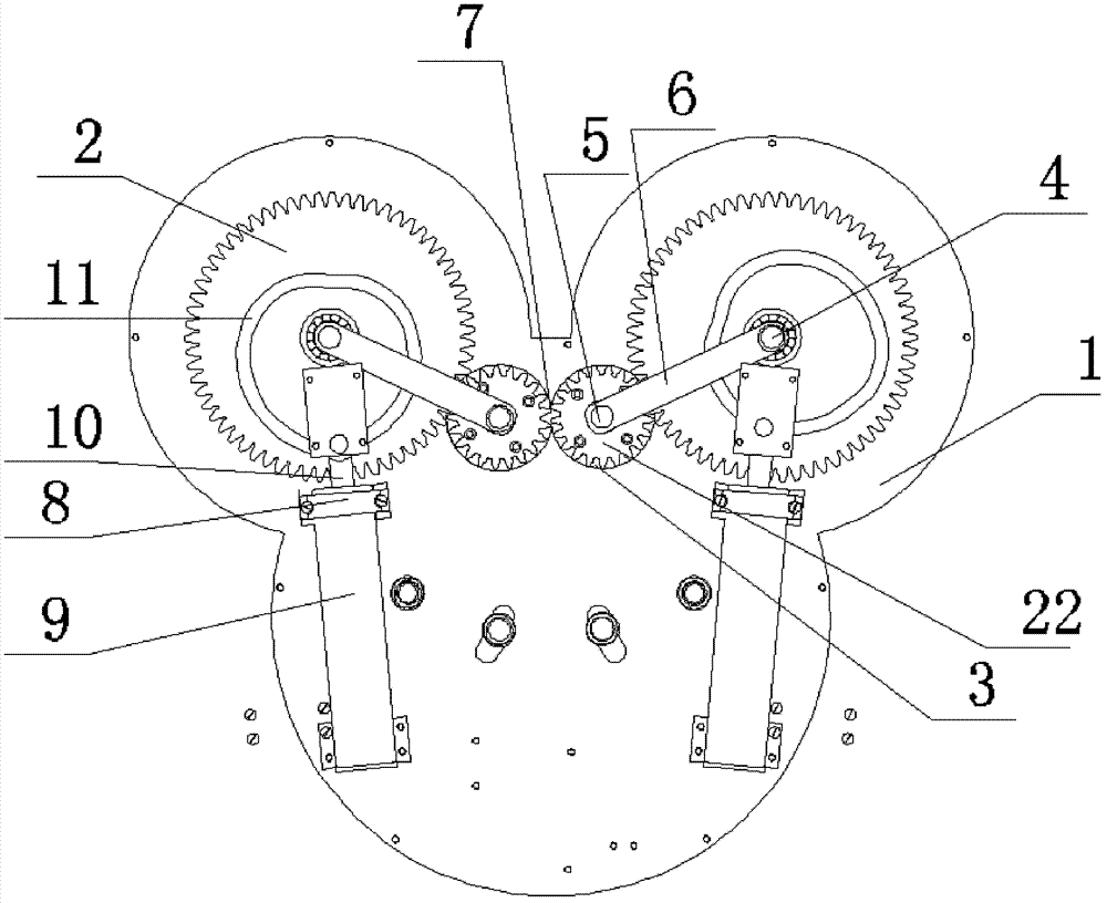
[0027] An escape and rescue slow down device, including a housing 1, a clamping mechanism and a deceleration mechanism. The clamping mechanism and the deceleration mechanism are arranged in the housing 1; the clamping mechanism includes a pair of large gears 2 symmetrically arranged , 1 pair of small gears 22 and 1 pair of pulleys 3, wherein a large gear 2 and a small gear 22 are arranged on the same side, and the large gear 2 on the same side meshes with the small gear 22, and the large gear 2 is fixedly installed on the shaft 4 In the housing 1, the large gear shaft 4 and the pinion shaft 5 are connected by a connecting rod 6; the pinion 22 on the same side is installed coaxially with the pulley 3; a pair of symmetrically arranged pulleys 3 forms a through rope hole 7; The angle between the connecting rod 6 and the horizontal is an acute angle;
[0028] The reduction mechanism includes a pair of piston dampers 8, which are respectively installed under the two large gears 2. ...
Embodiment 2
[0030] As described in embodiment 1, the escape and rescue descending device differs in that:
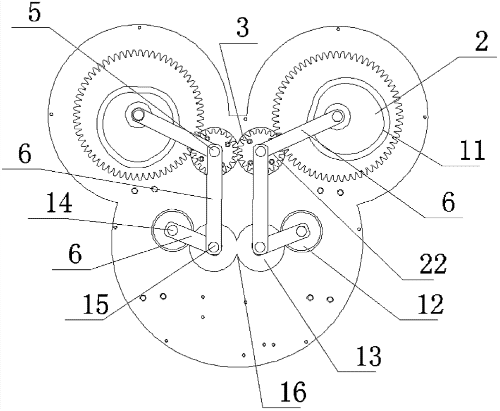
[0031] The clamping mechanism also includes a pair of fixed rollers 12 and a pair of movable pulleys 13 symmetrically arranged, wherein one fixed roller 12 and one movable pulley 13 are arranged on the same side, and the fixed roller 12 on the same side is in phase with the movable pulley 13 Cut, the fixed roller 12 is fixedly installed in the housing 1 through the shaft 14, the fixed roller shaft 14 on the same side is connected with the movable pulley shaft 15 through the connecting rod 6, and a pair of symmetrically arranged movable pulleys 13 forms a through auxiliary rope The hole 16 is up and down opposite to the said rope hole 7, and the pinion shaft 5 on the same side is connected to the movable pulley shaft 15 through the connecting rod 6. The connecting rods 6 on the same side form three sides of a parallelogram, which can be deformed to reduce the distance between the opp...
Embodiment 3
[0033] As described in Embodiment 2, the escape and rescue descending device differs in that:
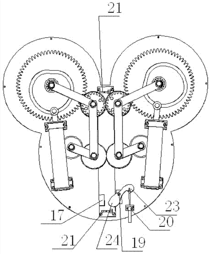
[0034] The escape rescue slow descender also includes an eccentric cam speed regulating device arranged below the rope hole, and the eccentric cam speed regulating device includes a fixed clamping block 17 and a movable clamping block 18, and the fixed clamping block 17 is fixed Set on the shell 1, the movable clamping block 18 is set on the shell 1 through the bolt 19, one end 24 of the movable clamping block is connected with the shell 1 through the spring 20, and the other end 23 of the movable clamping block is connected with the fixed The clamping blocks 17 are oppositely arranged. The fixed clamping block 17 and the movable clamping block 18 in the eccentric cam speed regulating device are normally closed and tightened, and are used to tighten the rescue rope. The rescue rope of the whole body can realize the purpose of self-controlling the descending speed: the spring deform...
PUM
 Abstract
Description
Claims
Application Information
 - R&D
- Intellectual Property
- Life Sciences
- Materials
- Tech Scout
- Unparalleled Data Quality
- Higher Quality Content
- 60% Fewer Hallucinations
Browse by: Latest US Patents, China's latest patents, Technical Efficacy Thesaurus, Application Domain, Technology Topic, Popular Technical Reports.
© 2025 PatSnap. All rights reserved.Legal|Privacy policy|Modern Slavery Act Transparency Statement|Sitemap|About US| Contact US: help@patsnap.com


