A punching machine mechanism with magnetic drive

A technology of magnetic transmission and punching machine, applied in the field of punching machinery, can solve the problems of low frequency of punching, low production efficiency, complex mechanism, etc., and achieve the effects of low cost, high production efficiency and simple mechanism

Inactive Publication Date: 2011-12-14
赵佰成
View PDF0 Cites 0 Cited by
  • Summary
  • Abstract
  • Description
  • Claims
  • Application Information

AI Technical Summary

Problems solved by technology

[0002] At present, the transmission mode of stamping machinery adopts the transmission mode of crank-link mechanism. The stamping machine with this transmission mode not only has the disadvantages of complex mechanism and high cost, but also relies on mechanical transmission. Generally not high, so there is still a shortcoming of low production efficiency

Method used


Image

  • A punching machine mechanism with magnetic drive
  • A punching machine mechanism with magnetic drive

Examples


Embodiment Construction

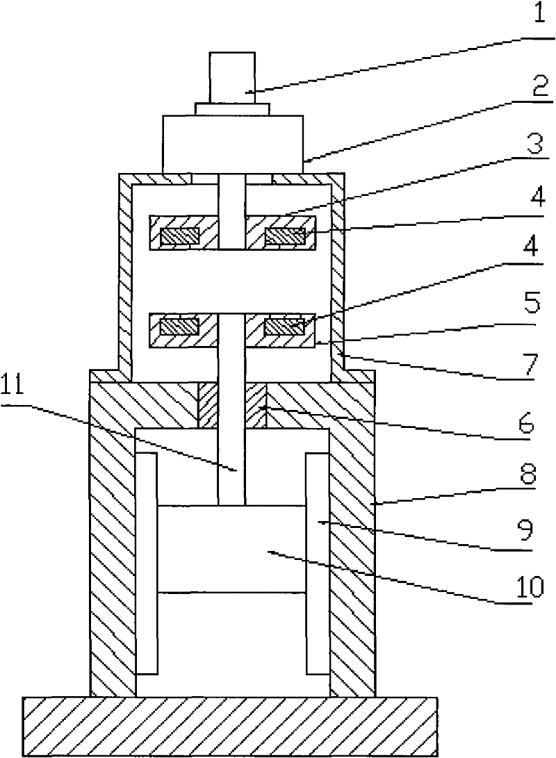
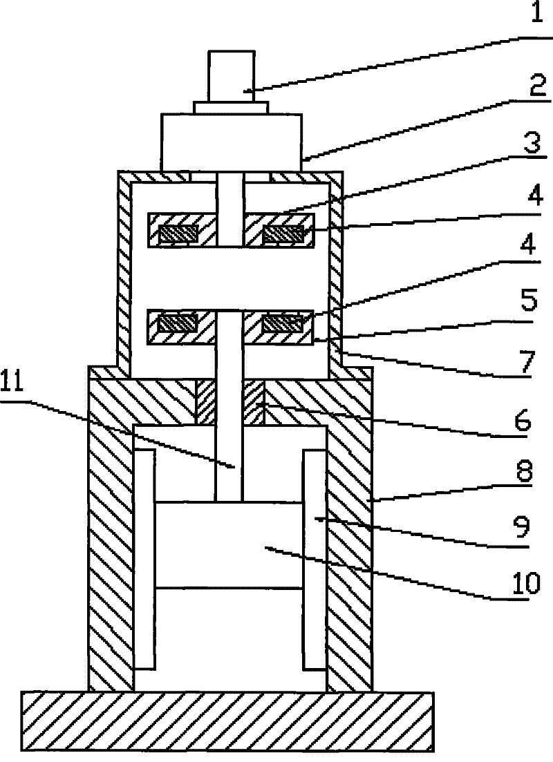
[0009] The stamping machine mechanism has a slider (10), the slider (10) is installed on the fuselage (8) through the guide rail (9), and a sliding bearing (6) is installed on the top of the fuselage (8), and the drive shaft (11) Pass through the sliding bearing (6) and connect with the slider (10) through the bottom of the drive shaft (11). A drive disc (5) is installed on the top of the drive shaft (11), and the polarity of the magnet (4) On the contrary, it is symmetrically embedded in the drive disc (5); a drum support (7) is installed on the top of the fuselage (8), and the center line of the drum support (7) is concentric with the center line of the drive disc (5). The rotating disk (3) is installed on the output shaft of the reducer (2), and the magnet (4) is inlaid in the rotating disk (3) with opposite polarity and symmetrically; a reduction box is installed on the upper part of the drum support (7) (2), the frequency conversion motor (1) is connected with the reducti...


PUM


Abstract

A punching machine mechanism with magnetic transmission, which is composed of a frequency conversion motor, a reduction box, a rotating disk, a magnet, a driving disk, a sliding bearing, a barrel bracket, a body, a guide rail, a slider, and a driving shaft; the punching machine mechanism has a Slider, the slider is installed on the fuselage through guide rails, a sliding bearing is installed on the top of the fuselage, the driving shaft passes through the sliding bearing, and is connected with the slider through the bottom of the driving shaft, and a sliding bearing is installed on the upper part of the driving shaft The drive plate, the polarity of the magnet is opposite, symmetrically embedded in the drive plate; a barrel bracket is installed on the top of the fuselage, the center line of the barrel support is concentric with the center line of the drive plate, and the rotating plate is installed on the output of the reducer On the shaft, the polarity of the magnet is opposite and symmetrically embedded in the rotating disk; a reduction box is installed on the upper part of the drum support, and the frequency conversion motor is connected with the reduction box.

Description

technical field [0001] The invention relates to a mechanism of a stamping machine, in particular to a mechanism of a stamping machine driven by magnetic force, and belongs to the technical field of stamping machinery. Background technique [0002] At present, the transmission mode of stamping machinery adopts the transmission mode of crank-link mechanism. The stamping machine with this transmission mode not only has the disadvantages of complex mechanism and high cost, but also relies on mechanical transmission. Generally not high, so there is still a shortcoming of lower production efficiency. Contents of the invention [0003] The object of the present invention is to provide a magnetic drive punching machine mechanism, which overcomes the shortcomings of existing crank-connecting rod mechanical drive punching machines: complex structure and high cost; meanwhile, it is also to overcome the existing The stamping machine with crank connecting rod mechanical transmission e...

Claims


Application Information

Patent Timeline
Patent Type & Authority Applications(China)
IPC IPC(8): B30B1/42
Inventor 赵佰成
Owner 赵佰成
Why Eureka
Try Eureka