
A yarn twist tester

A tester and yarn technology, which is applied in the field of textile yarn twist testing and recording, can solve the problems of accurate, convenient and fast measurement of twist, large error in measurement results, and low degree of automation, and achieves complete functions and reliable performance. , advanced circuit design effect

Inactive Publication Date: 2011-12-14
TAICANG HONGDA FANGYUAN ELECTRIC
View PDF4 Cites 7 Cited by
  • Summary
  • Abstract
  • Description
  • Claims
  • Application Information

AI Technical Summary

Problems solved by technology

[0002] For the twist measurement of silk or yarn, a large part of the country is still at the stage of hand-operated twisters. During the measurement, the yarn or silk to be tested needs to be cut off and taken out from the twisting equipment together with the winding drum. In the laboratory, it is time-consuming and labor-intensive to calculate after winding up the hand twister in the laboratory; another way is to use the linear speed tester and the spindle speed tester to measure the rotation speed of the silk or yarn respectively according to the definition of twist, and then pass The twist is obtained by manual calculation, the degree of automation of the measurement process is also low, and the error of the measurement result is large; at present, there is also a flash tube used in a flash spindle speed tester that uses short-arc pulse xenon lamps, which consumes a lot of power and can only be used for long distances. Cable AC power supply; when using infrared direct detection of spindle speed to measure the twist, it needs to be stopped, and the spindle rod needs to be turned into a hole, etc., so that there are certain difficulties in the accurate, convenient and fast measurement of the twist

Method used


Image

  • A yarn twist tester
  • A yarn twist tester
  • A yarn twist tester

Examples


Embodiment 1

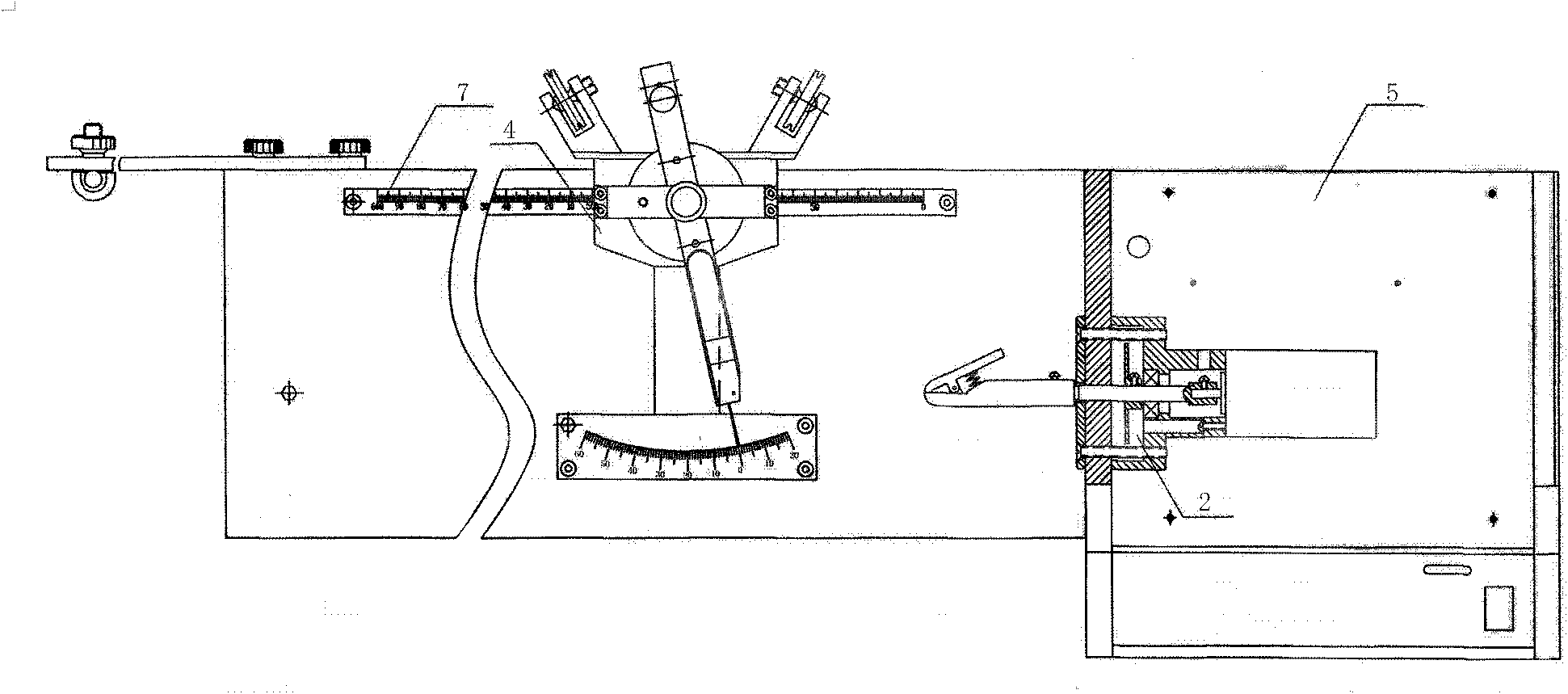
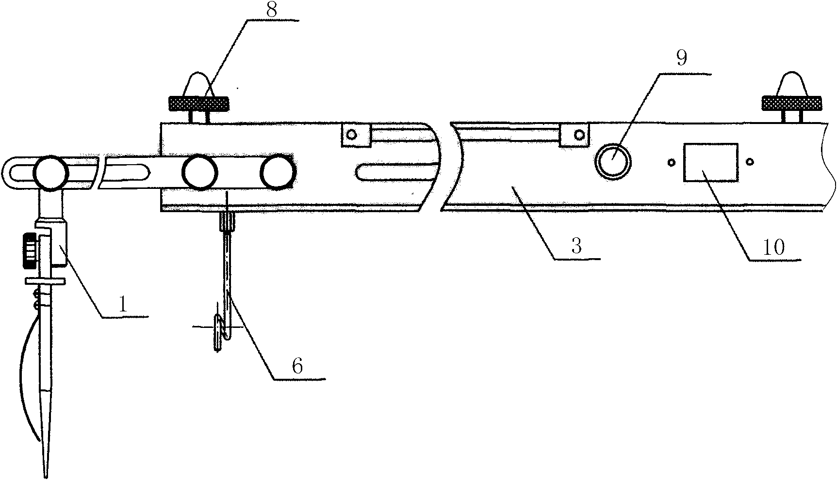
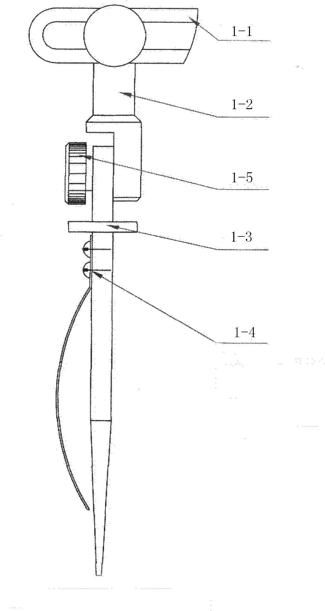
[0017] Example 1: A kind of yarn twist tester provided by the present embodiment, the structure is as follows: figure 1 and figure 2 As shown, it includes a creel assembly 1, a rotating chuck assembly 2, a chassis assembly 3 and a tension adjustment assembly 4. The two ends of the chassis assembly 3 are respectively fixed with the creel assembly 1 and the rotating chuck assembly 2 by bolts. One end of the chuck assembly 2 is provided with a machine head joint 5, and a tension adjustment assembly 4 is installed horizontally on the upper surface of the chassis assembly 3 between the creel assembly 1 and the rotary chuck assembly 2, and on the chassis assembly at one side of the creel assembly. Also be vertically installed with yarn guide hook 6, the top of yarn guide hook is " z " shape, and the bottom yarn guide hook seat of yarn guide hook and chassis assembly 3 adopt bolt connection and fix.

[0018] like image 3 and Figure 4 As shown, the creel assembly includes a wi...


PUM


Abstract

The invention relates to a yarn twist tester, which comprises a creel assembly, a rotary chuck assembly, a chassis assembly and a tension adjustment assembly. The two ends of the chassis assembly are respectively fixed with the creel assembly and the rotary chuck assembly by bolts. A tension adjustment assembly is installed horizontally on the upper surface of the chassis assembly between the assembly and the rotary chuck assembly, and a yarn guide hook is vertically installed on the chassis assembly at one side of the creel assembly. The invention has simple appearance, advanced circuit design, high integration, reliable performance, complete functions, and simple operation. The mechanical part adopts the internationally popular horizontal pulley balance swing structure, which is directly loaded with tension and can adapt to a wide range of twists. Test experiment.

Description

technical field [0001] The invention relates to a yarn twist tester, belonging to the technical field of textile yarn twist testing and recording. Background technique [0002] For the twist measurement of silk or yarn, a large part of the country is still at the stage of hand-operated twisters. During the measurement, the yarn or silk to be tested needs to be cut off and taken out from the twisting equipment together with the winding drum. In the laboratory, it is time-consuming and labor-intensive to calculate after winding up the hand twister in the laboratory; in addition, there is another way to measure the rotation speed of the silk or yarn with the line speed tester and the spindle speed tester respectively according to the definition of twist, and then pass The twist is obtained by manual calculation, the degree of automation of the measurement process is also low, and the error of the measurement result is large; there is still a flash tube used in the flash spindle...

Claims


Application Information

Patent Timeline
Patent Type & Authority Applications(China)
IPC IPC(8): D01H13/32D01H13/10
Inventor 周介明
Owner TAICANG HONGDA FANGYUAN ELECTRIC
Learn More