washing machine
A technology for washing machines and cylinders, applied in the field of washing machines, can solve the problems of twisted leads and inability to eliminate stress, etc.
- Summary
- Abstract
- Description
- Claims
- Application Information
AI Technical Summary
Problems solved by technology
Method used
Image
Examples
no. 1 approach
[0038] Refer below Figure 1 to Figure 12 The washing machine according to the first embodiment will be described.
[0039] first, Figure 11 The middle shows the overall structure of the drum type washing machine as a washing machine. On the front of the washing machine frame 1 ( Figure 11 The roughly central part of the middle right side) forms a laundry entrance 2, and a door 3 for opening and closing the entrance 2 is provided.
[0040] In addition, an operation panel 4 is provided on the upper part of the front portion of the washing machine housing 1, and a control device 5 for operation control is provided on the back side thereof (inside the washing machine housing 1).
[0041] Inside the washing machine housing 1, a water tank 6 is arranged. The water tank 6 is axially front and rear ( Figure 11 The water tank 6 is elastically supported on the bottom plate 1a of the washing machine frame 1 by a pair of left and right (only one side in the figure) suspensions 7 ...
no. 2 approach
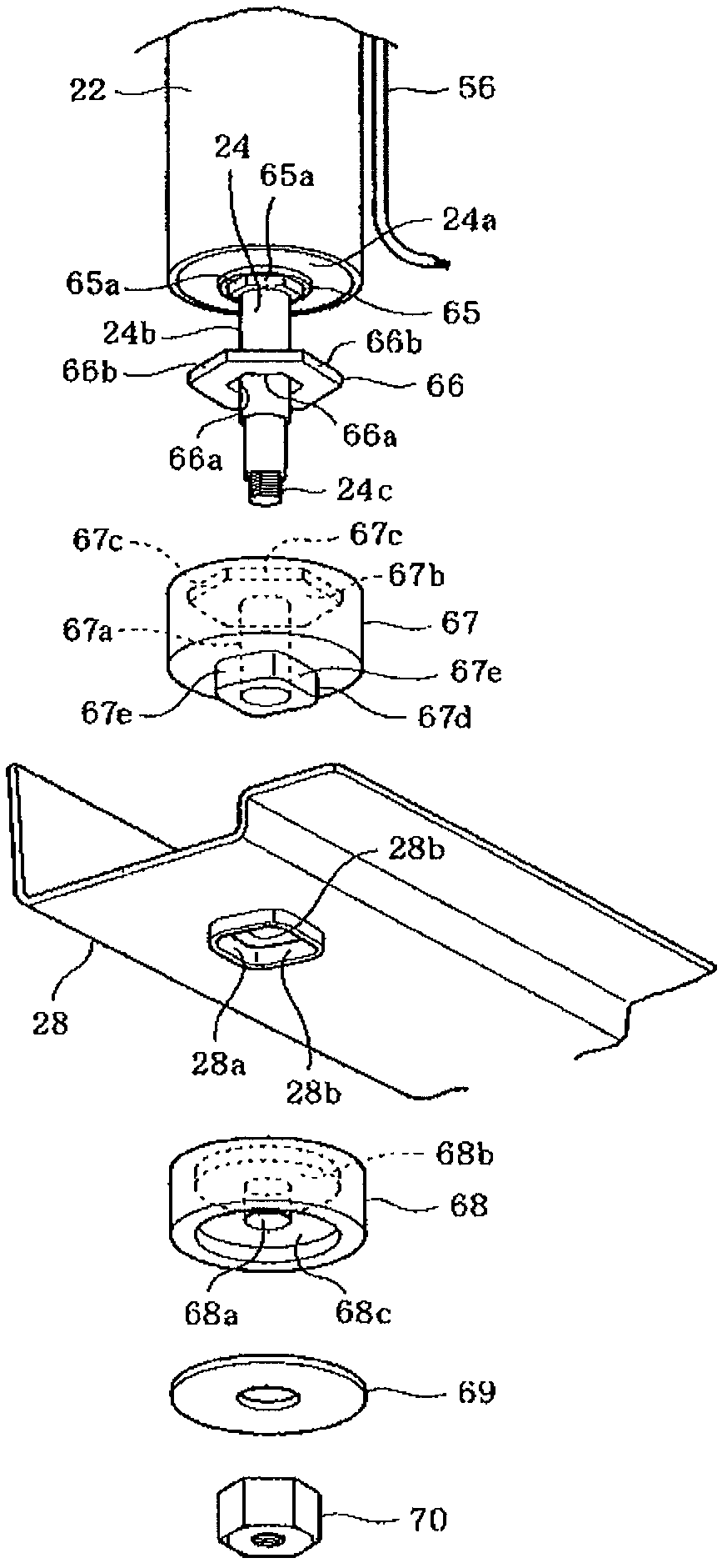
[0158] Although in this embodiment, the configuration in which the lead wire 56 is led out from the slightly upper portion of the cylinder 22 is illustrated (refer to figure 1 with Figure 12 ), but also as Figure 13 Lead out from the bottom of the cylinder 22 as shown. In this way, the transition portion from the damper 21 to the bottom plate 1a of the washing machine housing 1 can be shortened, and the stress acting on the wiring can be reduced.
[0159] In addition, as an embodiment of the washing machine, it is not limited to a drum type washing machine, and may be a so-called vertical washing machine including a rotary tank inside a vertical water tank and an agitator in the rotary tank.
[0160] According to the washing machine of the above-mentioned embodiment, the lead wire drawn out from the damper can be prevented from being twisted.
no. 3 approach
[0162] Second, refer to Figure 14 to Figure 19 A third embodiment will be described.
[0163] first of all, yes Figure 19 The overall structure of the drum type washing machine shown (hereinafter simply referred to as washing machine) will be described. In the front part ( Figure 19 The roughly central part of the middle right side) forms a laundry entrance 2, and a door 3 for opening and closing the entrance 2 is provided. In addition, an operation panel 4 is provided on the upper part of the front surface of the housing 1, and a control device 5 for operation control is provided on the back side thereof.
[0164] Inside the housing 1, a water tank 6 is arranged. The water tank 6 is axially front and rear ( Image 6 The water tank 6 is elastically supported on the bottom plate 1a of the frame body 1 in an inclined shape on the front side by a pair of left and right (only one shown in the figure) suspensions 7 (details will be described later).
[0165] A motor 8 is att...
PUM
 Abstract
Description
Claims
Application Information
 - R&D
- Intellectual Property
- Life Sciences
- Materials
- Tech Scout
- Unparalleled Data Quality
- Higher Quality Content
- 60% Fewer Hallucinations
Browse by: Latest US Patents, China's latest patents, Technical Efficacy Thesaurus, Application Domain, Technology Topic, Popular Technical Reports.
© 2025 PatSnap. All rights reserved.Legal|Privacy policy|Modern Slavery Act Transparency Statement|Sitemap|About US| Contact US: help@patsnap.com


