Self-fixed support member and truss using the self-fixed support member

A technology for supporting components and trusses, which is applied in the field of self-fixing supporting components and trusses using the self-fixing supporting components, can solve the problems of construction and cross-section weakening, labor and time-consuming, and large amount of screws, etc., and achieves convenient processing and transportation, Improve assembly efficiency and reduce the number of screws

Inactive Publication Date: 2011-12-14
重庆中瑞鑫安实业有限公司
View PDF3 Cites 7 Cited by
  • Summary
  • Abstract
  • Description
  • Claims
  • Application Information

AI Technical Summary

Problems solved by technology

Metal webs are generally welded, bolted, and screwed. Since the webs and chords are thin, it is very inconvenient to use welding operations. The use of bolts will lead to weakening of the construction and section, while the amount of screws used for screw connections is very small. Large, labor-intensive and time-consuming

Method used


Image

  • Self-fixed support member and truss using the self-fixed support member
  • Self-fixed support member and truss using the self-fixed support member
  • Self-fixed support member and truss using the self-fixed support member

Examples


Embodiment 1

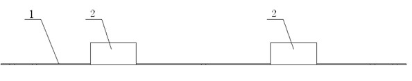
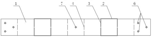
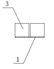
[0033] figure 1 is a front view of a self-fastening support member for a second chord, figure 2 is a top view of a self-fastening support member for a second chord, image 3 It is a left view of a self-fastening support member suitable for two chords; as shown in the figure, the self-fastening support member of this embodiment is suitable for fastening two chords, which includes a strip plate 1, and the strip-shaped Two partitions 2 are vertically arranged on one side of the board 1, and the partitions 2 are distributed at intervals along the length direction of the strip 1, and the strip 1 can be folded toward the side provided with the partition 2 (along the crease line). 4) After connecting into a closed structure, the closed structure formed after folding is as follows Figure 4 shown.

[0034] In this embodiment, the partition 2 is arranged parallel to the length direction of the strip plate 1; of course, the partition can also be perpendicular to the length direction...

Embodiment 2

[0044] The difference between this embodiment and Embodiment 1 lies in the number of partitions 2 , the self-fastening support member of this embodiment is suitable for fastening four chords, and a four-chord truss is obtained by assembling.

[0045] In the present invention, the chord is not limited to the chord with a square cross-section as shown in the figure, and the chord can also be a steel pipe processed from cold-formed steel; Made of high-strength metal plates; the number of partitions is one or more, depending on the number of chords to be fastened; when assembling the truss, at least one self-fastening support member is used to connect the fastening chords, according to the number of chords Depending on the length or actual use requirements, multiple self-fastening support members can be arranged along the length direction of the chord.


PUM


Abstract

The invention discloses a self-clamping supporting member and a truss using the same. The self-clamping supporting member comprises a strip-shaped plate, wherein at least one clapboard is vertically arranged on one face of the strip-shaped plate, and is distributed at certain intervals along the length direction of the strip-shaped plate; the strip-shaped plate can be folded towards one face of the clapboard and connected into an enclosed structure; and in the folding process of the strip-shaped plate, a chord member is put into a space encircled by the folded strip-shaped plate and the clapboard and is tightly clamped by the strip-shaped plate and the clapboard, so that the truss can be assembled. The chord member is tightly clamped by the member under the action of the friction force ofthe strip-shaped plate and the clapboard (further comprising a baffle plate), so that chord members can be tightly connected with each other without welding, bolts and the like, the quantity of screws is reduced remarkably, and half mechanical and fully-mechanical assembly can be performed conveniently, and the truss assembling efficiency is increased.

Description

technical field [0001] The invention relates to a building component and a beam-column component using the building component, in particular to a self-fixing support component and a truss using the self-fixing support component. Background technique [0002] A traditional light steel truss includes two metal chords arranged side by side, and the two chords are connected by at least one metal web. Metal webs are generally welded, bolted, and screwed. Since the webs and chords are thin, it is very inconvenient to use welding operations. The use of bolts will lead to weakening of the construction and section, while the amount of screws used for screw connections is very small. Big, more labor-intensive and time-consuming. [0003] Therefore, it is necessary to design a self-clamping support member, which can be used to connect and fasten the chords, so as to improve the assembly efficiency of the truss while ensuring the strength of the truss. Contents of the invention [0...

Claims


Application Information

Patent Timeline
Patent Type & Authority Applications(China)
IPC IPC(8): E04B1/38E04C3/00
Inventor 罗来安杜盛安曹辉
Owner 重庆中瑞鑫安实业有限公司
Why Eureka
Try Eureka