Precast elements for cast-in-place concrete

A technology of prefabricated components and cast-in-place concrete, which is applied to building components, building structures, floor slabs, etc., and can solve problems such as one-time cast-in-place molding

Inactive Publication Date: 2011-12-14
湖南华廷筑邦住宅工业有限公司
View PDF10 Cites 3 Cited by
  • Summary
  • Abstract
  • Description
  • Claims
  • Application Information

AI Technical Summary

Problems solved by technology

In this way, when the cast-in-place concrete prefabricated components are applied to the cast-in-place concrete floor, the lower end of the beam formwork is lower than that of the rib formwork, and there is a beam-rib connection form between the beam bottom formwork and the rib formwork, and the beam formwork is flush with the rib formwork The part is the upper formwork of the beam, and the lower part of the beam formwork than the rib formwork is the lower formwork of the lower hanging beam, and its top plate is a forming form for post-casting concrete. The cast-in-place concrete rib formwork is formed by combining the formwork and its rib bottom formwork. After the cast-in-place concrete is poured, the cast-in-place concrete floor slab is poured on the top plate, which can form a large-span one-way cast-in-place prefabricated beam-rib floor. This prefabricated component solves the problem of Solved the problem that the large-span beam-rib structure in the prior art could not be cast-in-place after setting prefabricated components

Method used


Image

  • Precast elements for cast-in-place concrete
  • Precast elements for cast-in-place concrete
  • Precast elements for cast-in-place concrete

Examples


Embodiment Construction

[0071] The present invention will be further described below in conjunction with the accompanying drawings and embodiments.

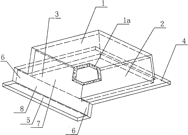
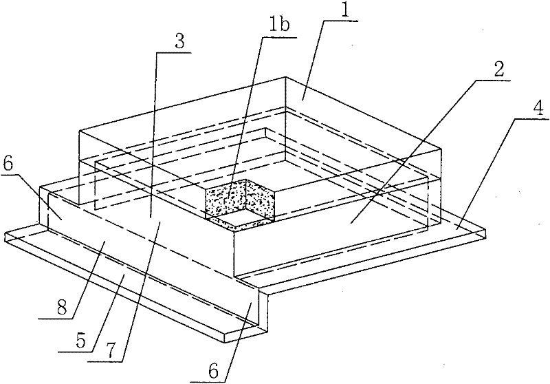
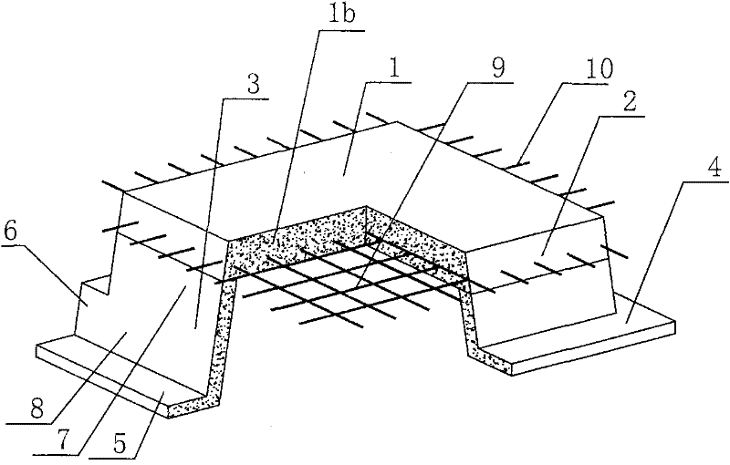
[0072] The invention is attached figure 1 As shown, the prefabricated component for cast-in-place concrete includes roof, rib formwork, and beam formwork, and the roof plate, rib formwork and beam formwork form a member with one side opening, which is characterized in that only one beam formwork is provided, and the lower end of the rib formwork extends outwards. The lower end of the beam formwork protrudes outwards to form the bottom formwork of the beam. The lower end of the beam formwork is lower than the lower end of the rib formwork. There is a beam-rib connection form between the beam formwork and the rib formwork. The beam formwork and the rib formwork The flush part is the upper mold of the beam, the lower part of the beam mold than the rib mold is the lower mold of the lower hanging beam, and the top plate is a forming mold for post-pouring con...


PUM


Abstract

The prefabricated component for cast-in-place concrete includes roof (1), rib formwork (2), beam formwork (3), and the roof plate (1), rib formwork (2) and beam formwork (3) form a member with one side open, and It is characterized in that only one beam formwork (3) is provided, the lower end of the rib formwork (2) protrudes outward to form a rib base formwork (4), and the lower end of the beam formwork (3) protrudes outwards to form a beam base formwork (5), The lower end of the beam formwork (3) is lower than the lower end of the rib formwork (2), and the beam-rib connection formwork (6) is arranged between the beam end formwork (5) and the rib end formwork (4), and the beam formwork (3) and the rib formwork ( 2) The flush part is the beam upper formwork (7), the part of the beam formwork (3) lower than the rib formwork (2) is the lower hanging beam formwork (8), and its top plate (1) is the forming formwork (1a) for post-pouring concrete .

Description

a technical field [0001] The invention relates to prefabricated components for cast-in-place concrete. Two background technology [0002] At present, many buildings adopt the method of cast-in-place concrete hollow floor slabs. The cast-in-place concrete floor slab can solve the problems of anti-seismic and cracking, but a large number of templates are used during construction, which not only increases the cost, but also slows down the construction speed and prolongs the construction period. Patent No. ZL00203695.9 is a utility model patent for "combined concrete hidden rib floor slab". It is composed of prefabricated thin plates, formwork, hidden ribs, and upper plates. The shell, the formwork includes the upper plate and the surrounding side plates, there are hidden ribs between the adjacent prefabricated thin plates or formwork, the upper plate covers the formwork, and is connected with the hidden ribs as a whole, and as the applicant applied for In the invention patent...

Claims


Application Information

Patent Timeline
Patent Type & Authority Applications(China)
IPC IPC(8): E04B5/18E04B5/19
Inventor 邱伯谦
Owner 湖南华廷筑邦住宅工业有限公司
Why Eureka
Try Eureka