Rotary steerable tool and its biasing mechanism and control method for the biasing mechanism

A rotary steering and tool technology, applied in the automatic control system of drilling, directional drilling, earth-moving drilling, etc., can solve problems such as the instability of the drilling platform, the pressure drop of the drilling fluid, and the ability of the drilling fluid to purify the wellbore, etc. The effect of accurate guidance and stable system operation

Active Publication Date: 2011-12-14
CHINA UNIV OF PETROLEUM (BEIJING)
View PDF8 Cites 21 Cited by
  • Summary
  • Abstract
  • Description
  • Claims
  • Application Information

AI Technical Summary

Problems solved by technology

During the drilling process, the non-zero vertical component causes the borehole to expand and the drilling efficiency to decrease
[0005] (2) Drilling platform instability
[0006] (3) When drilling, the high-pressure drilling fluid continuously erodes the upper and lower disc valves, on the one hand, it is easy to damage the disc valves; on the other hand, the pressure of the drilling fluid decreases, reducing the ability of the drilling fluid to purify the borehole

Method used


Image

  • Rotary steerable tool and its biasing mechanism and control method for the biasing mechanism
  • Rotary steerable tool and its biasing mechanism and control method for the biasing mechanism
  • Rotary steerable tool and its biasing mechanism and control method for the biasing mechanism

Examples


Embodiment 1

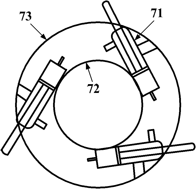
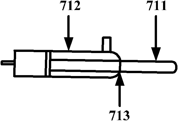
[0038] This embodiment firstly provides a biasing mechanism for a rotary guiding tool. Wherein, a plurality of hydraulic support implements of the biasing mechanism are installed on the outer cylinder of the biasing mechanism. Hydraulic support equipment mainly includes hydraulic support ribs, asymmetric hydraulic cylinders, displacement sensors, etc. The hydraulic support tool pushes the support rib out of the outer cylinder through the pressure difference between the left and right chambers of the asymmetric hydraulic cylinder and reaches the well wall. During the operation, the displacement sensor detects the displacement of the support rib in real time. On the shaft wall, the reaction force of the shaft wall to the supporting rib is used as the disturbance of the hydraulic position control system, so as to meet the given value of the control requirement.

[0039] Figure 1a It is a cross-sectional schematic diagram of a biasing mechanism according to an embodiment of the ...

Embodiment 2

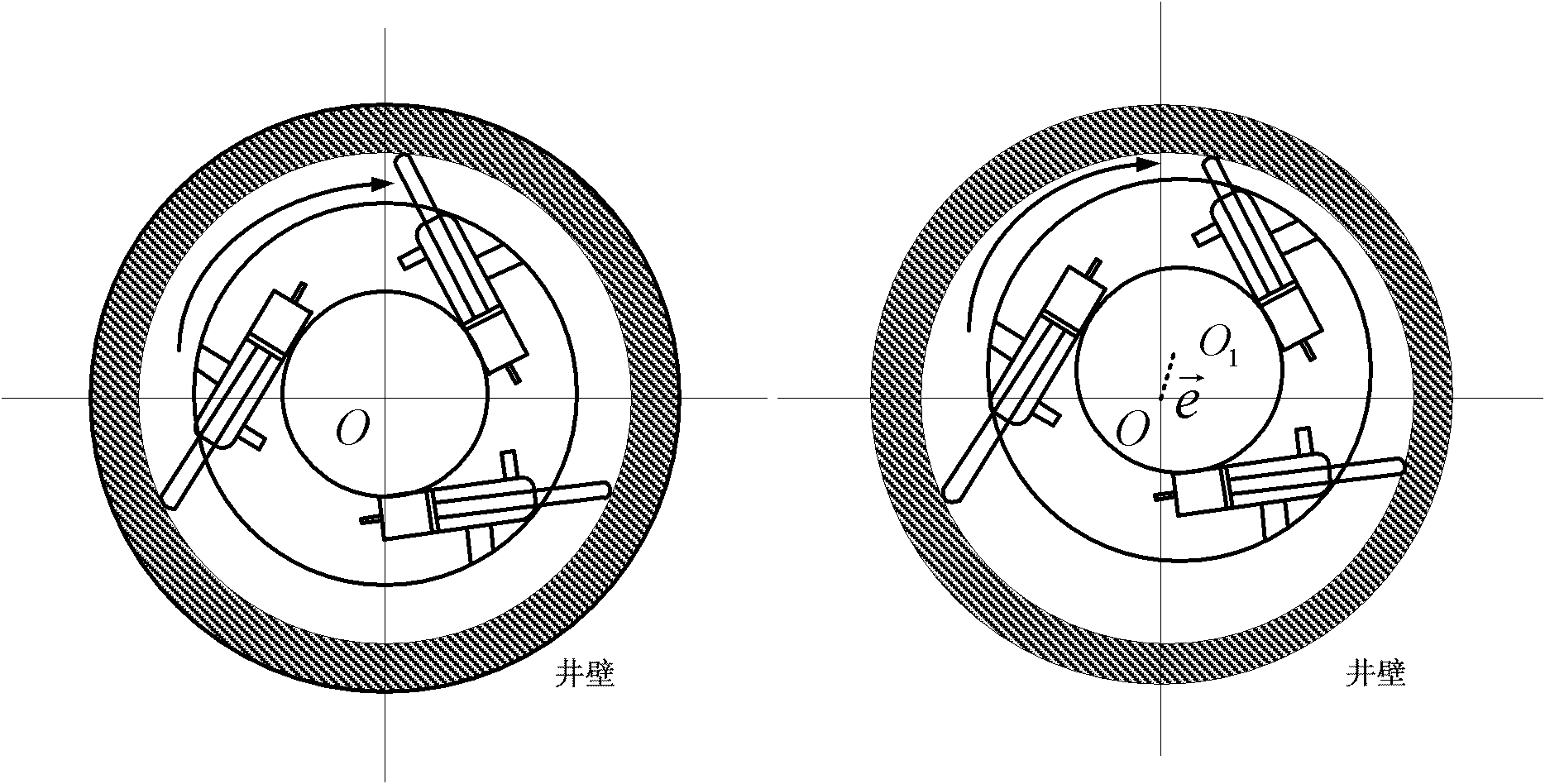
[0056]An embodiment of the present invention provides a rotary guiding tool including the biasing mechanism described in Embodiment 1. Figure 7 It is a structural schematic diagram of a rotary steerable tool according to an embodiment of the present invention. Figure 8 It is a schematic diagram of the offset mode of the rotary steerable tool according to the embodiment of the present invention. Such as Figure 8 As shown, the working mode of the offset mechanism of the rotary steering tool in this embodiment is a push-to-drill type, and the outer cylinder of the offset mechanism is rotating; the rotary steering tool in this embodiment adopts the "displacement working mode", and finally uses The drill bit produces an offset angle relative to the borehole axis to achieve steering.

[0057] Such as Figure 7 As shown, the rotary steering tool of this embodiment at least includes: the biasing mechanism 7 described in Embodiment 1 and the hydraulic control system (included in ...


PUM


Abstract

The invention discloses a rotating steering tool, a deflection mechanism thereof and a control method for the deflection mechanism. The deflection mechanism comprises an outer barrel and a plurality of hydraulic support tools. The outer barrel is connected with a drill of the rotating steering tool, and rotates together with the drill. The plurality of hydraulic support tools are arranged on the inner sidewall of the outer barrel. Each hydraulic support tool comprises a support wing rib, an asymmetrical hydraulic cylinder and a displacement sensor, wherein one end of the support wing rib is positioned on the support tool, and the other end of the support wing rib is extended out of the outer barrel; the asymmetrical hydraulic cylinder drives the extension and retraction motions of the support wing rib by adopting a hydraulic difference, and controls the support wing rib to be extended out of the outer barrel according to target extension and retraction displacement and pressed againstthe well wall of a bored well; and the displacement sensor measures the actual displacement of the extension of the support wing rib in real time and feeds the actual displacement back to a hydrauliccontrol system of the rotating steering tool, so that the hydraulic control system can perform closed loop control on the actual displacement of each support wing rib according to the target extension and retraction displacement.

Description

technical field [0001] The invention relates to the technical field of petroleum drilling, in particular to a rotary steerable tool, a biasing mechanism thereof and a control method for the biasing mechanism. Background technique [0002] Rotary steerable drilling technology is a cutting-edge automatic drilling technology developed in the 1990s, representing the most advanced drilling technology in the world. The rotary steerable system can complete drilling operations under difficult conditions, and its appearance will revolutionize the drilling industry. Drilling practice in foreign countries has proved that the popularization and application of rotary steerable drilling technology in difficult wells, horizontal wells, extended-reach wells, high-deviation wells, and three-dimensional multi-target wells not only improves the drilling speed, but also reduces drilling accidents, thereby reducing Drilling costs. [0003] The actuator of the mature dynamic push-by rotary stee...

Claims


Application Information

Patent Timeline
Patent Type & Authority Applications(China)
IPC IPC(8): E21B7/04E21B44/00
Inventor 左信杨全进岳元龙伍玉麒魏萍徐宝昌
Owner CHINA UNIV OF PETROLEUM (BEIJING)
Why Eureka
Try Eureka