An Intelligent Casing Pliers with Back Tongs

A technology of casing tongs and backup tongs, which is applied in the direction of casing, drill pipe, drilling equipment, etc., can solve the problems of safety doors without protection devices, low degree of automation, and low safety guarantee, so as to increase the practical range, reduce labor intensity, The effect of improving quality

Inactive Publication Date: 2011-12-14
金华萨博思石油机械有限公司
View PDF4 Cites 17 Cited by
  • Summary
  • Abstract
  • Description
  • Claims
  • Application Information

AI Technical Summary

Problems solved by technology

The current casing tongs have the following disadvantages: the degree of automation is low, and the labor intensity of the workers is high; the workers are too close to the construction site, and there is no protection device for the safety door, so the safety guarantee is low; it is difficult to align the casing threads during work, which is easy to cause Sticking and tooth damage affect the quality of work; when the main tong is used in conjunction with the backup tong, the device moves and it is difficult to clamp the casing

Method used


Image

  • An Intelligent Casing Pliers with Back Tongs
  • An Intelligent Casing Pliers with Back Tongs
  • An Intelligent Casing Pliers with Back Tongs

Examples


Embodiment 1

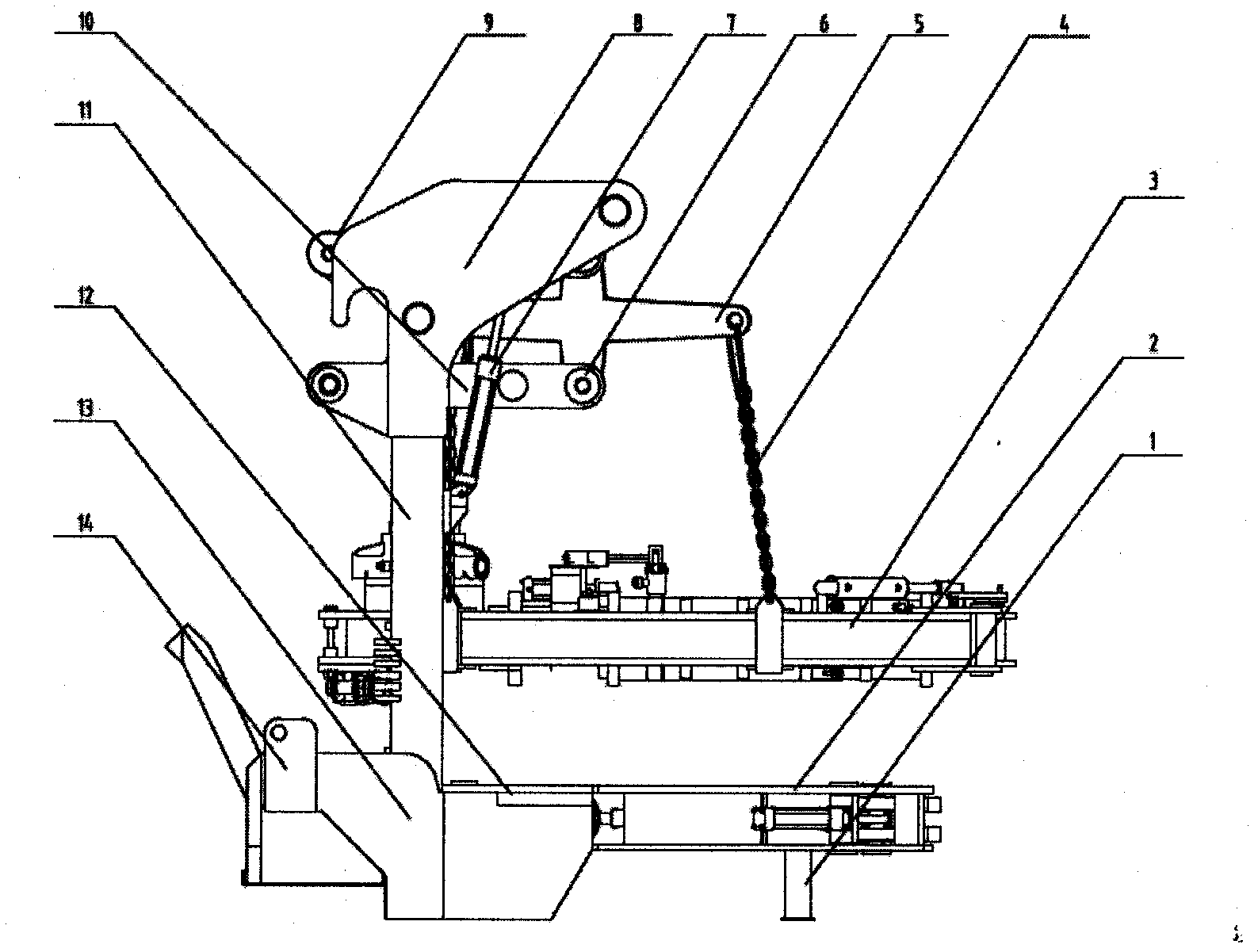
[0019] Example 1: Combining Figure 1-Figure 7 , the present invention is an intelligent casing tong with a backup tong, which is composed of a main frame, a hanger, a main tong (3) and a back tong (2), and the main tong (3) is connected to the back tong (2) On the main frame, the main tongs (3) are suspended on the hanger connected to the main frame by chains (4), and the back tongs (2) are welded to the main frame and supported by two feet (1).

[0020] The present invention also has the following technical characteristics:

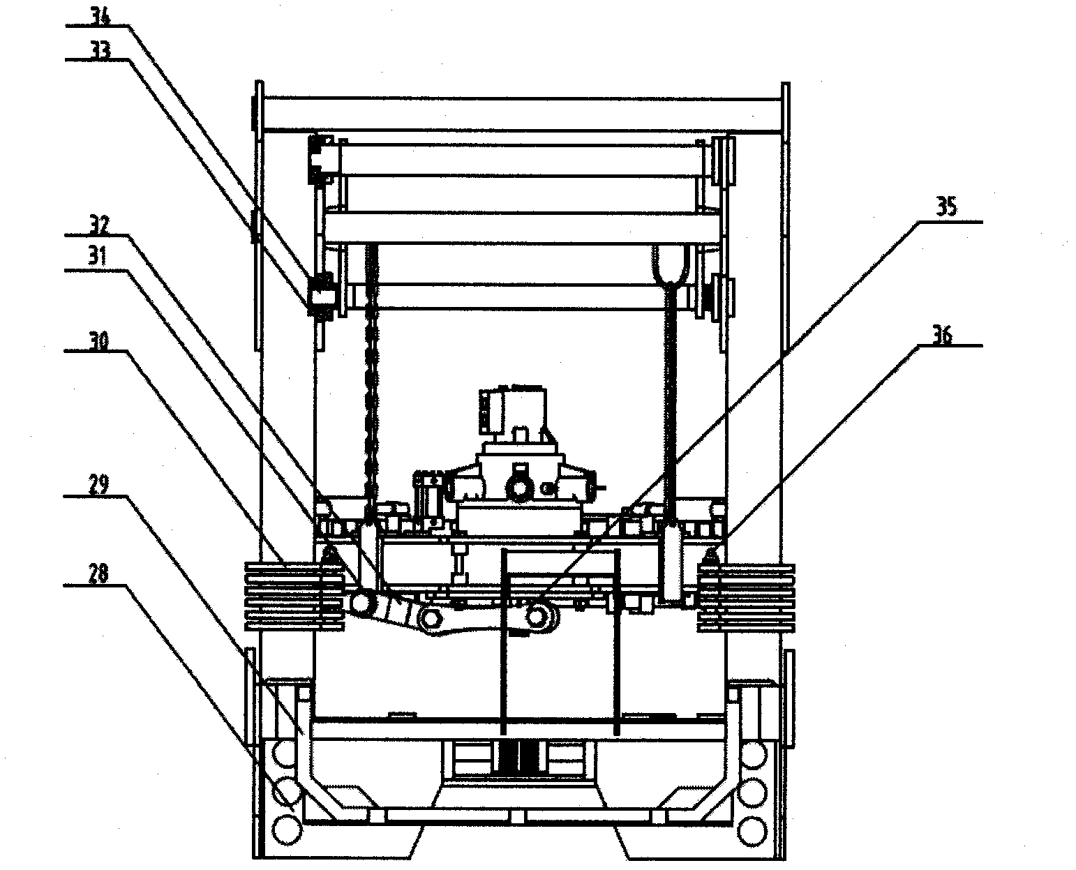
[0021] The hanger is a parallelogram structure, including a hanging plate (5), an upper plate (20), a lower plate (10), a rear beam (19), two front beams (17), a first flange (6) , the second flange (16), the third flange (21), the fourth flange (33) and short pins (34), the hanging plate (5) is enclosed within two front beams (17), and the front beam ( 17) It is hingedly connected with the upper plate (20) and the lower plate (10), the rear beam (19)...

Embodiment 2

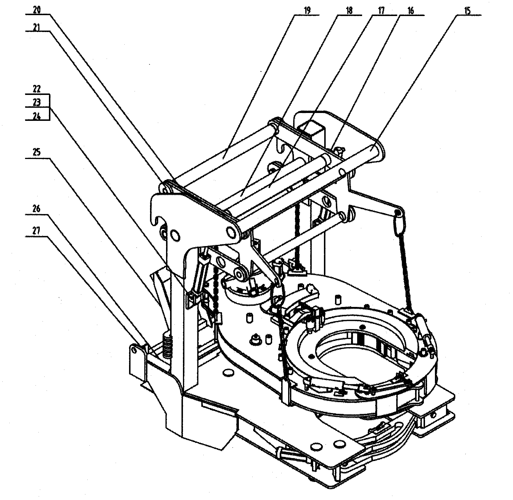
[0025] Example 2: Combining Figure 1-Figure 7 , the present invention realizes the full automation of the working process. The shift fork hydraulic cylinder (239) controls the switching of the fast and slow gears of the power tongs. A travel switch is installed on the shift fork hydraulic cylinder (239) to detect the switching situation of the gear positions. The left safety door (250) is opened and closed by the left door cylinder (248), and the pressure protection after the door is closed is provided by the left door cylinder (248). The left safety door is installed on a roller shaft. The two ends of the left hydraulic cylinder are connected by clevis, and the afterbody is installed on the clevis shaft of the upper plate (227), and the piston rod end clevis is connected on the clevis shaft of the left safety door (250). The right safety door (257) is symmetrical with respect to the left safety door (250), and can be opened and closed by the right door cylinder (260). In...


PUM


Abstract

The invention provides intelligent casing tongs with back-up tongs, which comprises a main frame, a hanging frame, main tongs and back-up tongs, wherein the main tongs and the back-up tongs are connected on the main frame; the main tongs are suspended on the hanging frame through a chain, which is connected with the main frame; the back-up tongs are welded with the main frame and supported by two feet; the hanging frame is parallelogram-shaped; a rotary torque measuring device is mounted to the main frame; the main tongs achieve the effect of clamping a casing in a claw climbing manner; the back-up tongs are tightly clamped by three claws; and the claws are distributed in a mode of 120 degrees. The purpose of full-range automation of work of casing tongs is achieved, and the labor intensity of workers and accident incidence are reduced. The parallelogram-shaped hanging frame is adopted to ensure horizontal movement of power tongs. The tooth alignment process is centralized by adjusting a support cylinder. The back-up tongs improve the clamping force of the claws by use of a wedging mechanism. The back-up tongs are flexibly connected with the main tongs and can be detached to be used alone. The types of the claws are changed to fit different tube diameters, so as to increase the application range.

Description

(1) Technical field [0001] The invention relates to oil drilling equipment, in particular to an intelligent casing tong with a back tong. (2) Background technology [0002] At present, most of the power tongs used in oilfield workover are manually controlled by hydraulic reversing valves to control the start and stop of the power tongs. The switch of the safety door and the high and low gear control of the power tong are also generally manually controlled by the worker. When working, the power tongs are generally suspended on a movable suspension beam by a chain, and the worker moves to the casing, and adjusts the alignment of the casing thread by the worker's vision. The main tong and the back-up tong are often separated, and it is inconvenient to use the main tong and the back-up tong together. Even if the back-up tong is equipped, the centering of the casing thread is achieved by the fixed mechanical connection of the main tong and the back-up tong. The current casing t...

Claims


Application Information

Patent Timeline
Patent Type & Authority Applications(China)
IPC IPC(8): E21B19/16
Inventor 孙敬颋白勇刘春来孙鹏飞闫志超侯大兴
Owner 金华萨博思石油机械有限公司
Why Eureka
Try Eureka