Eureka AIR delivers breakthrough ideas for toughest innovation challenges, trusted by R&D personnel around the world.

hydraulic sleeve

A hydraulic sliding sleeve and hydraulic technology, applied in the direction of wellbore/well components, sealing/package, earthwork drilling and production, etc., can solve the problems of increased operation time of the pipe string, increased completion cost, and sliding sleeve not opened, etc. Achieve the effect of reducing resistance, reducing friction and ensuring reliability

Active Publication Date: 2011-12-14
CNOOC ENERGY TECH & SERVICES
View PDF6 Cites 10 Cited by
  • Summary
  • Abstract
  • Description
  • Claims
  • Application Information

AI Technical Summary

Problems solved by technology

For example, the opening or closing of the sliding sleeve can only be realized by using a separate running tool. Not only is this operation risky, the sliding sleeve may not be opened (or closed), and it is necessary to run an additional string to increase the working time. At the same time It also increases the cost of completion

Method used


Image

  • hydraulic sleeve
  • hydraulic sleeve
  • hydraulic sleeve

Examples


Embodiment Construction

[0016] In order to further understand the invention content, characteristics and effects of the present invention, the following examples are given, and detailed descriptions are as follows in conjunction with the accompanying drawings:

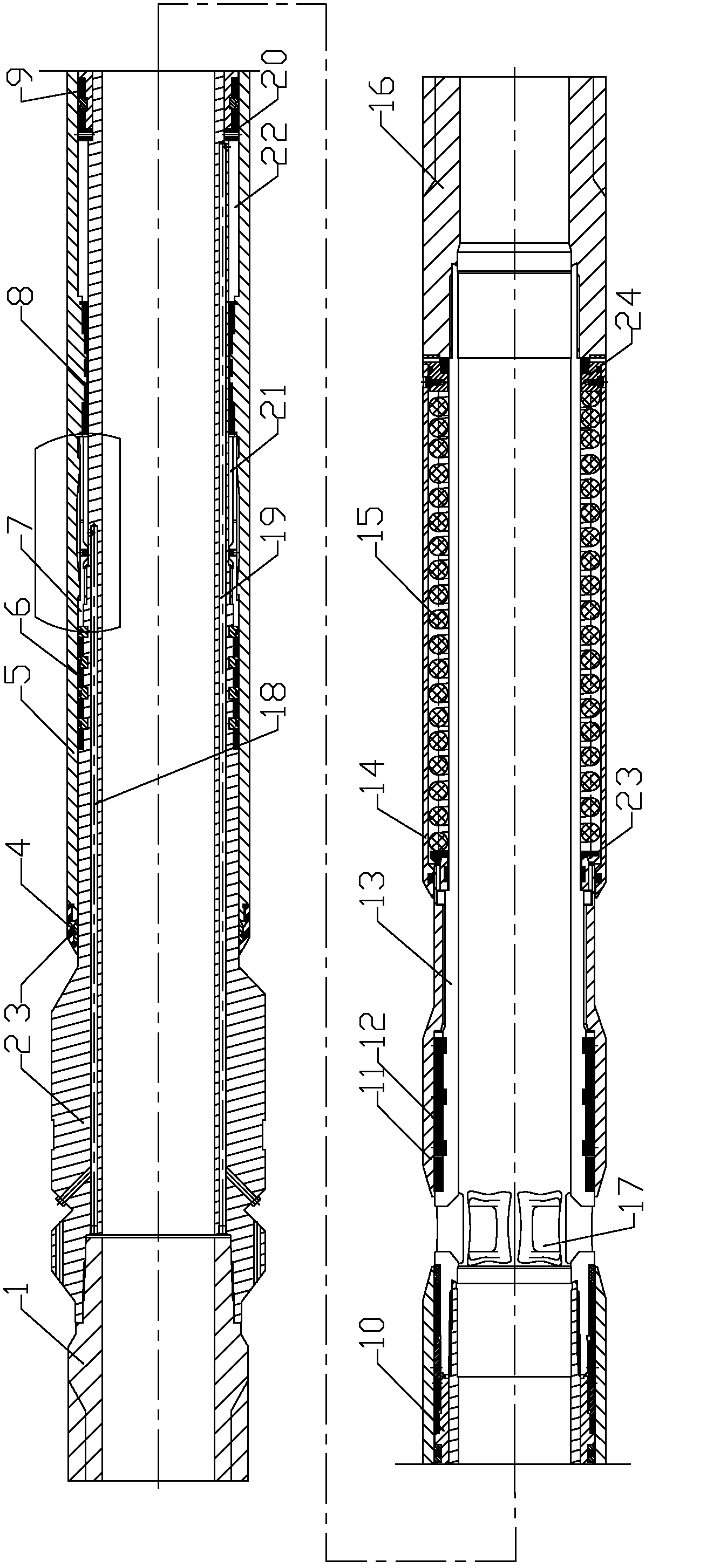
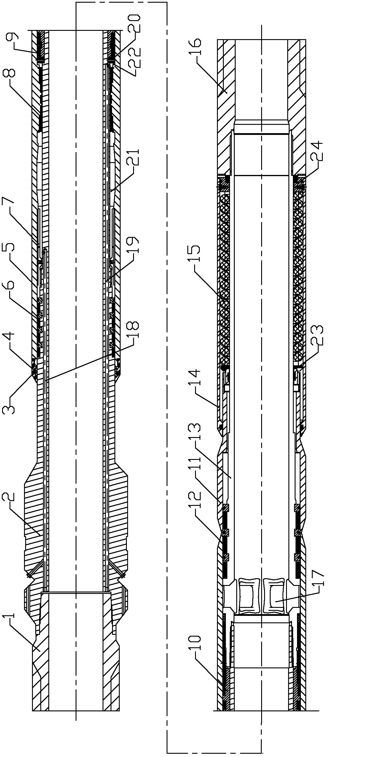
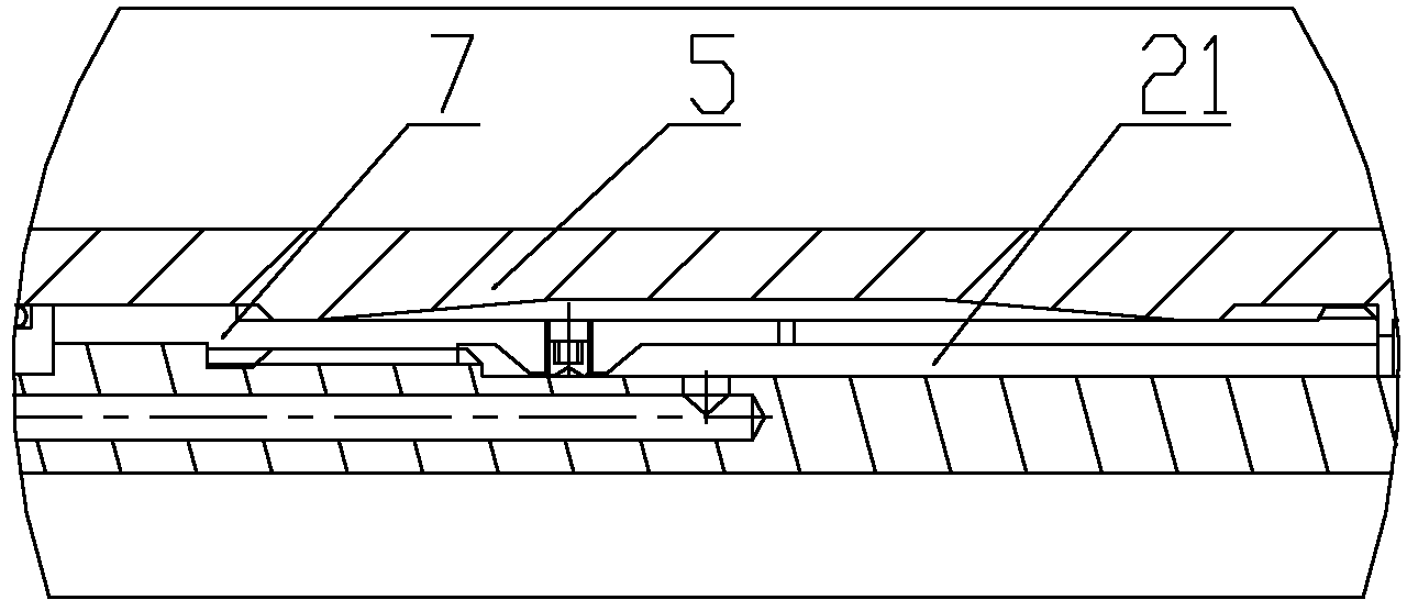
[0017] see figure 1 , a hydraulic sliding sleeve includes an upper main shaft 2, the upper main shaft is a cylindrical shape with two ends through, the upper end of the upper main shaft is connected with an upper joint 1, the lower part of the upper main shaft is threaded with a lower main shaft 13, and the upper part of the lower main shaft is provided with a radial The oil extraction hole 17, the lower end of the lower main shaft is connected with the lower joint 16,

[0018] A first hydraulic passage 18 and a second hydraulic passage 19 are provided on the cylinder wall of the upper main shaft. The first hydraulic passage and the second hydraulic passage are parallel to the center line of the upper main shaft. The middle part of the inner...


PUM


Abstract

The invention relates to a hydraulic sliding sleeve, comprising an upper spindle, wherein the tube wall of the upper spindle is provided with a first hydraulic channel and a second hydraulic channel which are parallel to a central line, an upper outer cylinder is sheathed outside the upper spindle, an upper part sealing combination, a middle part sealing combination and a lower part sealing combination arranged between the upper spindle and the upper outer cylinder divide a space between the upper outer cylinder and the upper spindle into an upper hydraulic cavity and a lower hydraulic cavity, the first hydraulic channel is communicated with the upper hydraulic cavity, the second hydraulic channel is communicated with the lower hydraulic cavity, and the upper outer cylinder can slide up and down by suppressing the upper hydraulic cavity and the lower hydraulic cavity. The invention has the advantages that: the hydraulic sliding sleeve has a simple structure, is convenient to operate and is safe and reliable, and the hydraulic sliding sleeve can be opened and closed only by carrying out suppressing operation on a hydraulic pipeline.

Description

technical field [0001] The invention belongs to the technical field of oil well completion, in particular to the field of wellbore or well valve device operated by control fluid provided outside the wellbore, and especially relates to a hydraulic sliding sleeve. Background technique [0002] At present, in the process of domestic oilfield development, there are many situations in which water content is different in different layers of the same well or in different layers of the same layer. poor effect. In addition, the development of many oilfields has entered the late stage of high water cut, and the properties of oil layers vary greatly. Conventional well completion technology cannot meet the normal production requirements of high water cut wells, leading to well shutdown. In order to solve the above problems, domestic and foreign personnel have done a lot of research. Someone proposed intelligent well completion technology, which can adjust the production layer without s...

Claims


Application Information

Patent Timeline
Patent Type & Authority Applications(China)
IPC IPC(8): E21B34/10
Inventor 张亮陈建兵马认琦刘传刚刘景超包陈义
Owner CNOOC ENERGY TECH & SERVICES
Why Eureka
Eureka Blog
Learn More