Speed ​​limit valve of automobile clutch control oil circuit

A speed-limiting valve, clutch technology, applied in the direction of clutches, fluid-driven clutches, non-mechanical drive clutches, etc., can solve the problem of not adjusting the clutch engagement speed, achieve the effect of simple structure, prevent frustration, and improve comfort

Inactive Publication Date: 2011-12-14
GREAT WALL MOTOR CO LTD
View PDF4 Cites 4 Cited by
  • Summary
  • Abstract
  • Description
  • Claims
  • Application Information

AI Technical Summary

Problems solved by technology

[0002] As a clutch control system for automobile products, quick separation and slow engagement are a basic requirement. To achieve this, domestic cars generally use a method of adding a buffer valve to the clutch control oil circuit to solve the problem. This method can only reduce oil pressure. pressure fluctuations to prevent the clutch pedal from vibrating, but has no effect on adjusting the clutch engagement speed

Method used


Image

  • Speed ​​limit valve of automobile clutch control oil circuit
  • Speed ​​limit valve of automobile clutch control oil circuit
  • Speed ​​limit valve of automobile clutch control oil circuit

Examples


Embodiment

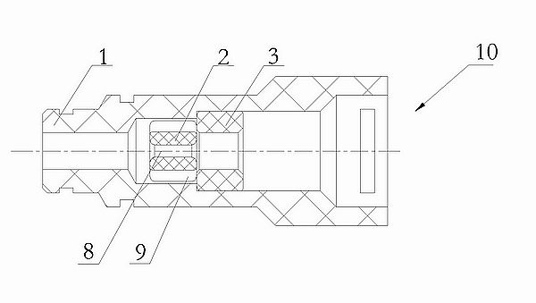
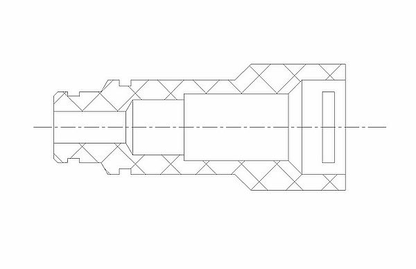
[0021] figure 1 Shown is a speed limiting valve 10 for an automobile clutch control oil circuit, which includes a valve body 1, a valve core 2 and a valve seat 3 coaxially arranged, wherein the valve core 2 has a central oil passage 8, and the central oil passage 8 for damping holes.

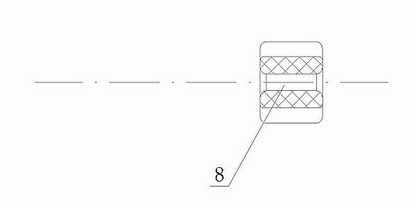
[0022] Such as image 3 and Figure 6 As shown, the radial structure of the spool 2 is in the shape of a "hollow ten" with arc-shaped edges, a central oil passage 8 in the center, and four bypass oil passages 9 . The structure of the spool 2 is equivalent to opening four evenly distributed radial depressions on the body of the cylindrical body and extending the bypass oil passage 9 along the axial direction. There is a hole in the center of the section (the shape of the hole is the radial cross-sectional shape of the central oil passage 8).

[0023] Such as Figure 4 As shown, the valve seat 3 is in the shape of a round tube, the lumen is the oil passage 8, and the inner diameter of the val...


PUM


Abstract

The invention discloses a speed-limiting valve for an automobile clutch control oil circuit, which comprises a valve core arranged on a coaxial line and provided with an oil passage, a valve seat and a valve body. Axially extending bypass oil passage; the valve seat is in the shape of a round tube. When the valve core and the valve seat are axially contacted and stacked, the bypass oil passage between the valve body and the valve core is completely blocked; Large three-stage central stepped hole, the front section is an oil passage, the middle section is used to match the valve core, the axial height is greater than the height of the valve core, and the rear section matches the valve seat. The invention can adjust the clutch engagement speed, improve riding comfort, prevent the feeling of frustration when shifting gears, and prevent the vehicle from stalling due to too fast clutch engagement speed when starting. It is convenient and suitable to be installed between the master cylinder and the working cylinder in the automobile clutch control system to adjust the separation and engagement speed of the clutch control mechanism.

Description

technical field [0001] The invention relates to an operating component for controlling the oil volume of an automobile to realize speed limiting, in particular to a speed limiting valve for an automobile clutch operating oil circuit. Background technique [0002] As a clutch control system for automobile products, quick separation and slow engagement are a basic requirement. To achieve this, domestic cars generally use a method of adding a buffer valve to the clutch control oil circuit to solve the problem. This method can only reduce oil pressure. Pressure fluctuations prevent the clutch pedal from vibrating, but it has no effect on adjusting the clutch engagement speed. Contents of the invention [0003] The technical problem to be solved by the present invention is to provide a speed limiting valve for the clutch control oil circuit of an automobile, which can adjust the clutch engagement speed, improve riding comfort, prevent the feeling of frustration when shifting ge...

Claims


Application Information

Patent Timeline
Patent Type & Authority Applications(China)
IPC IPC(8): F16D25/12F15B13/02
Inventor 马德昆杨艳青
Owner GREAT WALL MOTOR CO LTD
Why Eureka
Try Eureka