
A P gear actuator of automobile transmission

A technology for automotive transmissions and actuators, applied to mechanical equipment, components with teeth, belts/chains/gears, etc., can solve the problems of unreliable parking, difficult installation and positioning, high speed of parking motors, etc., and achieve easy manufacturing and control, simple and compact structure, and improved reliability

Inactive Publication Date: 2011-12-14
CHONGQING TSINGSHAN IND
View PDF5 Cites 13 Cited by
  • Summary
  • Abstract
  • Description
  • Claims
  • Application Information

AI Technical Summary

Problems solved by technology

[0004] At present, in the parking mechanism of the automobile transmission that has been used, there are the following problems: the speed of the parking motor is generally high, and the power cannot be directly transmitted to the parking cam, so a small reducer needs to be arranged between the parking cam and the motor , which makes the structure of the parking motor complex, requires high precision, and is difficult to control; some use a cam structure to drive the parking pawl, which has problems such as difficult installation and positioning, and unreliable parking; in addition, the parking mechanism of most parking mechanisms The car ratchets are all installed on the axle shaft of the differential, and the resistance torque of the parking mechanism is relatively large, which makes the parking mechanism require higher strength, etc.
To sum up, the existing parking mechanism has shortcomings such as high strength requirements, difficult installation and positioning, difficult control, complex structure of the parking motor, and high precision requirements.

Method used


Image

  • A P gear actuator of automobile transmission
  • A P gear actuator of automobile transmission
  • A P gear actuator of automobile transmission

Examples


Embodiment Construction

[0020] The present invention will be further described below in conjunction with accompanying drawing.

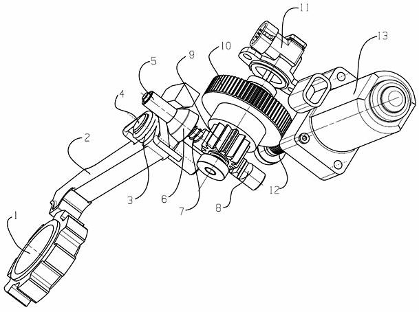
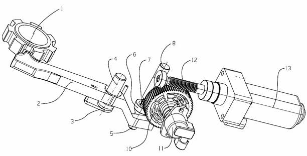
[0021] see figure 1 , figure 2 and image 3 The shown actuating mechanism for P gear of an automobile transmission includes a parking motor 13 arranged outside the transmission case, a worm gear assembly, a rack assembly, a parking ratchet 1 and a parking pawl 2 arranged inside the transmission case;

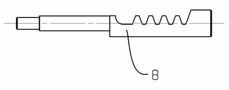
[0022] The rack assembly is composed of a rack shaft 8 and a parking cam limit sleeve 5, a parking cam 6 and a parking spring 7 which are successively arranged on the polished rod part of the rack shaft. One end of the parking spring 7 is connected to the rack shaft. The steps in the middle are close to each other, and the other end is close to the parking cam;

[0023] The worm gear assembly is composed of a worm gear 10 and a gear 9 arranged on the worm gear shaft. One end of the worm gear shaft stretches out from the transmission case and is connected with the P gear s...


PUM


Abstract

The invention discloses a P gear actuator of an automobile transmission, which includes a parking motor arranged outside the transmission case, a worm gear assembly, a rack assembly, a parking ratchet and a parking pawl, etc.; the rack assembly It is composed of a rack shaft, a parking cam limit sleeve, a parking cam and a parking spring; the worm gear assembly is composed of a worm gear and a gear set on the worm shaft, and one end of the worm shaft extends out of the transmission case and is connected to the P gear sensor The gear of the worm gear assembly meshes with the rack part on the rack shaft of the rack assembly; the output end of the parking motor is connected with a worm, and the worm meshes with the worm wheel on the worm gear assembly; the parking cam and the parking pawl One end is close to, and the ratchet at the other end of the parking pawl is matched with the tooth groove on the parking ratchet that is connected to the transmission input shaft. The beneficial effect of the invention is that the structure is simple and compact, the overall performance is good, the reliability of the car parking is improved, and the manufacturing and control are easy, and the production cost is low.

Description

technical field [0001] The invention relates to a car transmission parking mechanism, in particular to a car parking system suitable for preventing cars from accidentally moving when parking on a slope. Background technique [0002] When the car is parked on a normal flat road, the driver only needs to pull on the handbrake to brake the whole vehicle; however, if the car is parked on a steep slope, the handbrake alone cannot fully function, and may There will be movement. Ordinary manual transmissions can ensure that the vehicle does not slip by shifting into a gear, but for automatic transmissions or transmissions driven by motors, measures must be taken to prevent accidents from happening, so a parking mechanism is required to brake the wheels. [0003] The parking mechanism is a safety device to prevent the vehicle from sliding. It acts on the transmission of the vehicle and locks the drive shaft of the transmission so that the vehicle can be parked at a certain position...

Claims


Application Information

Patent Timeline
IPC IPC(8): F16H63/34
Inventor 胡松严皓陈嗣国汪训定金良宽陈四奇周朝东
Owner CHONGQING TSINGSHAN IND
Learn More