Permanent Magnet Direct Control Valve and Its Application

A control valve, direct technology, applied in valve details, valve device, valve operation/release device, etc., can solve the problems of unreliable work, difficult to adjust flow, high process cost, and achieve light operation, easy promotion and wide application. Effect

Inactive Publication Date: 2011-12-14
钟逍虎
View PDF6 Cites 6 Cited by
  • Summary
  • Abstract
  • Description
  • Claims
  • Application Information

AI Technical Summary

Problems solved by technology

[0002] The permanent magnet control valve refers to a fully enclosed valve controlled by a permanent magnet. Its main advantage is that it does not need the necessary and vulnerable dynamic seals for traditional rod and shaft valves, and prevents the valve from leaking. However, in many published Among the current permanent magnet control valve technologies, there are very few commercialized ones. The reason is that some of them use low-efficiency magnetic drag methods such as rotation, instantaneous motion, axial polarity magnetic rings, and homotropic magnetic rings. The material cost is high and the work is extremely unreliable; they mostly adopt the working principle of "pressure difference control", either diaphragm type or piston type, and the permanent magnet indirectly controls the opening and closing of the valve by controlling the "pilot hole" with a small diameter , which brings defects such as complex structure, high process cost, difficulty in adjusting the flow rate, impurities in the fluid make it easy to block, easy to bite, etc.

Method used


Image

  • Permanent Magnet Direct Control Valve and Its Application
  • Permanent Magnet Direct Control Valve and Its Application
  • Permanent Magnet Direct Control Valve and Its Application

Examples


Embodiment 1

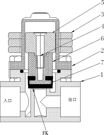
[0019] Embodiment one: according to figure 1 As shown, the valve seat 1 and the valve cover 2 are connected to form a statically closed valve body, a permanent magnet assembly 3 is provided outside the valve body, and only a valve plug assembly 4 is provided inside the valve, and an armature 5 is at one end of the valve plug assembly 4 , the middle is the extension rod 6, the other end is connected with the rubber valve plate 7, the rubber valve plate 7 is close to the valve port FK and closes the valve with the help of fluid pressure, when the permanent magnet assembly 3 moves upward, the valve plug assembly 4 follows upward The displacement opens the valve, and different displacements correspond to different flow rates.

Embodiment 2

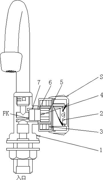
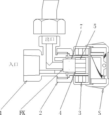
[0020] Embodiment two: according to figure 2 , image 3 As shown, the permanent magnet assembly 3 is installed in the handle S, which becomes the permanent magnet to directly control the faucet, or the permanent magnet to directly control the triangle valve. The method adopted in this embodiment is: radially fix a garden pin on the top of the valve cover 2 , the two ends or one end of the garden pin are inserted in the helical groove with several stair steps in the handle 6, when the handle 6 is rotated forward and reverse, the handle 6 will move the permanent magnet assembly 3 left and right, The valve plug assembly 4 in the valve also moves left and right to close and open the valve, and several stagnation steps correspond to different flow rates. image 3 The valve plug assembly 4 shown is only composed of an armature 5 and a valve plate 7 .

Embodiment 3

[0021] Embodiment three: according to Figure 4 As shown, the permanent magnet assembly 3 is connected with the floating ball F, which becomes the permanent magnet to directly control the liquid level valve. When the liquid level rises, the floating ball F can generate buoyancy to push the permanent magnet assembly 3 upward until the valve is closed. The gravity of the upper float F opens the valve when the liquid level drops.


PUM


Abstract

A permanent magnet direct control valve, comprising: a valve seat (1), a valve cover (2), a permanent magnet assembly (3), and a valve plug assembly (4) which is only installed in the valve, and the valve plug assembly (4 ) is used to directly close or open the valve port (FK). Application of permanent magnet direct control valve: The inlet, outlet and magnetic control position of the permanent magnet direct control valve can be selected arbitrarily, and the permanent magnet assembly (3) can be dragged in different ways to form a new product with different functions and excellent performance. The advantages of the permanent magnet direct control valve and its application of the present invention are: the permanent magnet direct control valve has simple structure, low cost, no wearing parts, zero leakage, brisk operation, high reliability and long life, and its application is very wide. Various functional products such as faucets, triangle valves, liquid level valves, foot valves, and fuel guns are easy to promote, and people are willing to accept them. A large number of such products will produce significant savings and low-carbon effects.

Description

technical field [0001] The invention relates to the technical field of water-saving and energy-saving appliances, in particular to a permanent magnet direct control valve and its application. Background technique [0002] The permanent magnet control valve refers to a fully enclosed valve controlled by a permanent magnet. Its main advantage is that it does not need the necessary and vulnerable dynamic seals for traditional rod and shaft valves, and prevents the valve from leaking. However, in many published Among the current permanent magnet control valve technologies, there are very few commercialized ones. The reason is that some of them use low-efficiency magnetic drag methods such as rotation, instantaneous motion, axial polarity magnetic rings, and homotropic magnetic rings. The material cost is high and the work is extremely unreliable; they mostly adopt the working principle of "pressure difference control", either diaphragm type or piston type, and the permanent mag...

Claims


Application Information

Patent Timeline
Patent Type & Authority Applications(China)
IPC IPC(8): F16K31/08
Inventor 钟荷清钟逍虎
Owner 钟逍虎
Why Eureka
Try Eureka