Distributed direct-mixing heat supply system

A heating system, distributed technology, applied in heating systems, hot water central heating systems, household heating, etc., can solve the problem that the design scale cannot meet the needs of development, reduce the transmission efficiency of the pipeline network, and affect the full utilization of heat, etc. problems, to achieve the effect of improving full utilization, improving transmission efficiency, and improving heat exchange efficiency

Inactive Publication Date: 2013-07-17
新疆西部热力集团有限公司
View PDF5 Cites 0 Cited by
  • Summary
  • Abstract
  • Description
  • Claims
  • Application Information

AI Technical Summary

Problems solved by technology

[0006] (1) The hydraulic balance of the main heating network loses a large amount of electric energy through the throttling adjustment of the excessive resource pressure head, and at the same time reduces the transmission efficiency of the pipe network
[0007] (2) The heat exchange efficiency of the secondary heat exchange system affects the full utilization of heat
[0008] With the rapid development of urban construction, the original design scale is far from meeting the needs of development; how to improve the transmission efficiency of the heat power network, how to improve the heat exchange efficiency of the heat exchange station, and at the same time, in line with the needs of energy saving and emission reduction, the original heat power network should be The system undergoes technical transformation

Method used


Image

  • Distributed direct-mixing heat supply system
  • Distributed direct-mixing heat supply system
  • Distributed direct-mixing heat supply system

Examples


Embodiment Construction

[0034] A distributed direct mixing heating system and its embodiments of the present invention will be described in detail below with reference to the accompanying drawings. All control instruments in the system are purchased from the market; a heat exchange station is equipped with a main console, and each control instrument completes its control tasks in the main console. The English symbols in the figure are numbers commonly used in this industry, and are symbols representing control functions. After reading the control instrument manual, those skilled in the art can understand its function and use, and can implement it.

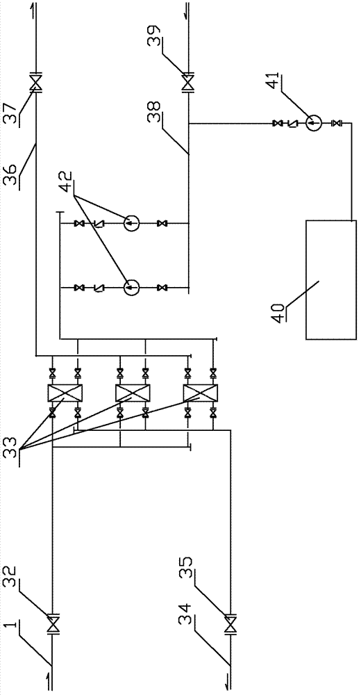
[0035] attached figure 1 It is a schematic diagram of the heat supply process for heat exchange with a traditional format heat exchanger. It belongs to the existing technology; it describes that the original heating network system in the heating area of ​​the traditional thermal power plant is a high-temperature water heating system of central heating "c...


PUM


Abstract

The invention discloses a distributed direct-mixing heat supply system. Primary high-temperature water as a heating medium of a main heat supply network is conveyed by adopting a centralized circulating system, high-temperature hot water of a primary main heat supply network enters a heat exchange station from a primary water supply pipeline 1, primary high-temperature hot water is mixed with secondary low-temperature water from a water mixing pipeline 14 after sequentially passing through a primary water supply stop valve 2, a primary water supply electromagnetic quick-break valve 3, a primary water supply electric regulating valve 4, an electromagnetic flow meter 5 and a primary water supply stop valve 7, and then is pushed by a secondary network circulating pump 15 and sent out througha pipeline 17 so that heat is transmitted to a user for heating; low-temperature water releasing the heat is returned from a pipeline 19, one part of the returned low-temperature water is pushed by awater pump 13 to be returned to the primary main heat supply network; and the other part of the returned low-temperature water flows through a pipeline 14 and is mixed with the primary high-temperature hot water for circularly supplying heat. The distributed direct-mixing heat supply system is provided with six automatic control subsystems, and has the advantages of eliminating invalid electric consumption in a conveying process, increasing conveying efficiency, effectively increasing heat exchange efficiency and fully utilizing heat.

Description

technical field [0001] The invention relates to a distributed direct-mix heating system, in particular to a direct-mix heating system in a heating area of ​​a thermal power plant, and belongs to the field of heat transmission. Background technique [0002] The original heating network system in the heating area of ​​most thermal power plants is a high-temperature water heating system of central heating "cogeneration". The circulation system transports heat medium to provide heat for each secondary exchange station for heating of system users. see figure 1 , The secondary heat exchange station adopts plate heat exchanger 33 for secondary heat exchange, and the water circulation of the secondary network system adopts the secondary pump 42 circulation system to provide heat for users. The constant pressure of the secondary network adopts the mechanical constant pressure method; the heat network system is a typical indirect heating system. [0003] The technological process p...

Claims


Application Information

Patent Timeline
Patent Type & Authority Patents(China)
IPC IPC(8): F24D3/10F24D3/02F24D19/10
Inventor 金明亮马卿仁孙德江刘关新金振刚
Owner 新疆西部热力集团有限公司
Why Eureka
Try Eureka