
Diaphragm pressure meter

A pressure gauge and diaphragm technology, applied in the direction of elastic deformation gauge type fluid pressure measurement, etc., can solve the problems affecting the measurement accuracy of the pressure gauge, buffer leakage, affecting the normal use of the pressure gauge, etc., and achieve the effect of improving the measurement accuracy.

Active Publication Date: 2011-12-14
BEIJING BRIGHTY INSTR +2
View PDF6 Cites 2 Cited by
  • Summary
  • Abstract
  • Description
  • Claims
  • Application Information

AI Technical Summary

Problems solved by technology

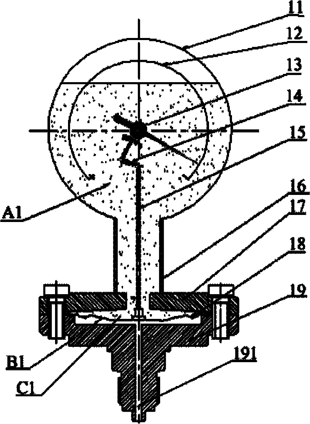
[0005] It can be seen from the working process and structural relationship of the above-mentioned diaphragm pressure gauge that the inner cavity A1 of the above-mentioned watch case 11, the inner cavity of the column 16, and the relative pressure chamber C1 are connected, and the buffer in the inner cavity A1 of the watch case 11 is directly The inner chamber of the column 16 is filled into the relative pressure chamber C1. Due to the pressure of the buffer solution on the diaphragm 18, the diaphragm 18 is depressed downward before there is no pressure of the measuring medium, which eventually leads to the deformation of the diaphragm 18 during measurement. Not proportional to pressure changes, thus affecting the accuracy of pressure gauge measurements
[0006] In addition, through the above-mentioned pressure gauge, the buffer solution is directly filled into the relative pressure chamber C1, and the buffer solution is easy to leak from between the diaphragm 18 and the upper contact body 17, which directly affects the normal use of the pressure gauge.

Method used


Image

  • Diaphragm pressure meter
  • Diaphragm pressure meter
  • Diaphragm pressure meter

Examples


Embodiment Construction

[0034] The invention provides a diaphragm pressure gauge, which improves the measurement accuracy of the existing diaphragm pressure gauge and prevents buffer fluid from leaking from between the diaphragm and the upper contact body.

[0035] The following will clearly and completely describe the technical solutions in the embodiments of the present invention with reference to the accompanying drawings in the embodiments of the present invention. Obviously, the described embodiments are only some, not all, embodiments of the present invention. Based on the embodiments of the present invention, all other embodiments obtained by persons of ordinary skill in the art without making creative efforts belong to the protection scope of the present invention.

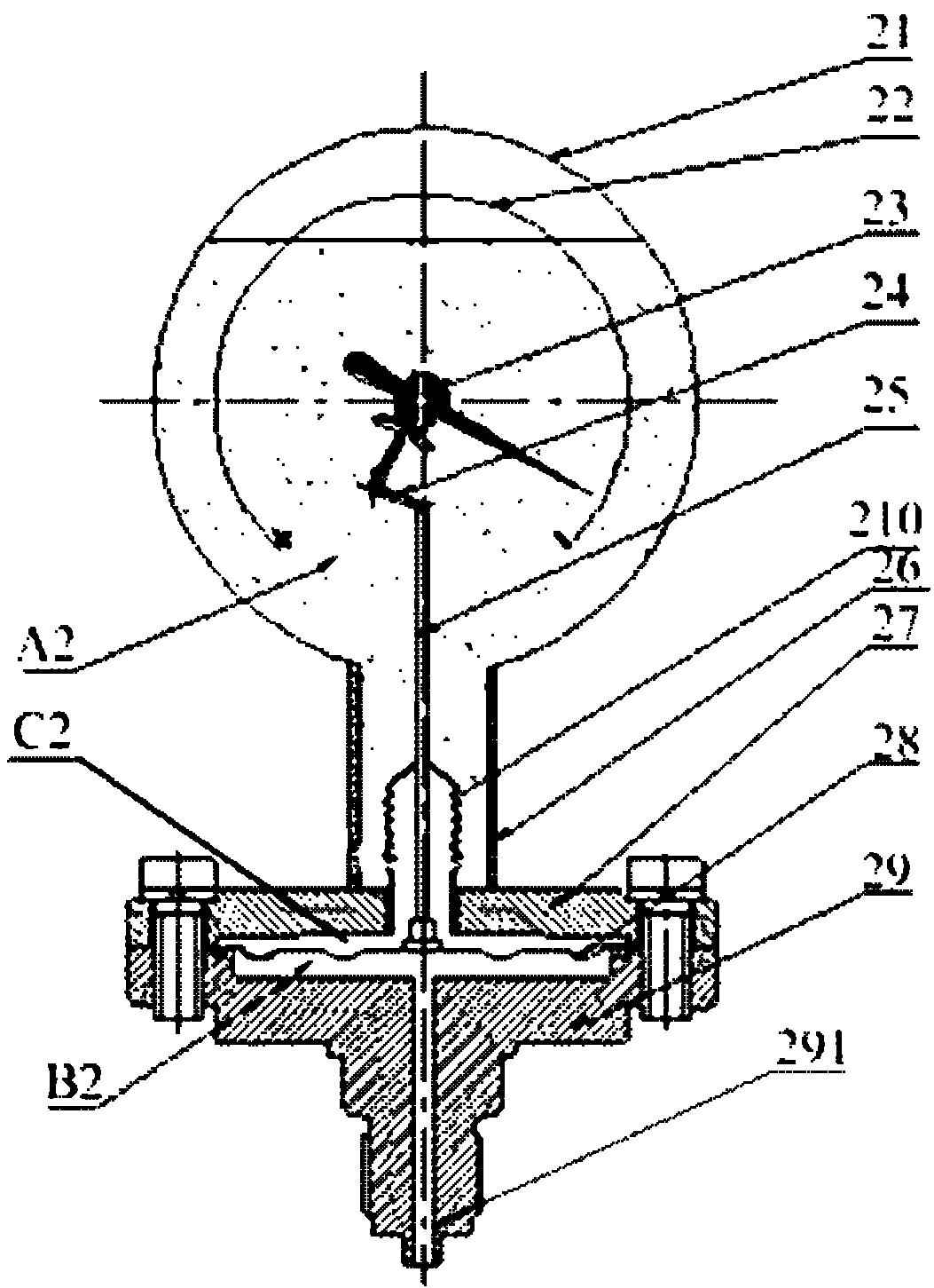
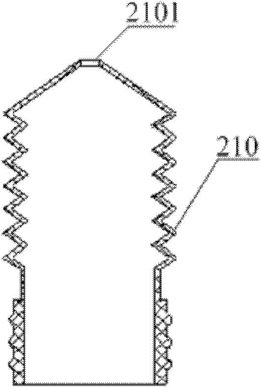
[0036] Please refer to the attached Figure 2-3 , figure 2 Schematic diagram of the structure of the diaphragm pressure gauge provided by the embodiment of the present invention; image 3 for figure 2 Schematic diagram of th...


PUM


Abstract

The invention provides a diaphragm pressure meter, comprising a meter shell (21) internally provided with a machine core (24); an upper connecting body (27) and a lower connecting body (29), which form a pressure cavity; a diaphragm (28) which divides the pressure cavity into a relative pressure cavity (C2) and a measuring medium cavity (B2), which are separated from each other; and a transfer rod (25) with two ends respectively connected with the machine core (24) and the diaphragm (28); the meter further comprises an separating component connected with the upper connecting body (27) for separating the inner cavity of the meter shell (21) from the relative pressure cavity (C2), and a hole is formed on the separating component; and the transfer rod (25) penetrates through the hole, and is connected with the separating component in a sealing manner. According to the diaphragm pressure meter disclosed by the invention, the measuring precision of the traditional diaphragm pressure meter is increased, and a buffer liquid is prevented from leaking between a slave diaphragm and the upper connecting body.

Description

technical field [0001] The present invention relates to the technical field of pressure measuring equipment, more specifically, to a diaphragm pressure gauge. Background technique [0002] Corrosion-resistant diaphragm pressure gauges are mainly used in the measurement of micro-pressures of gases and liquids in chemical, petroleum, and textile industries, especially for the measurement of micro-pressures of highly corrosive and viscous media (non-solidifying, non-crystalline media). [0003] The above-mentioned pressure gauges are often used in occasions with pulsating media or strong vibration environments, which requires certain protection measures for the instruments. Usually, the method of filling the watch case with buffer solution is adopted: the internal parts of the instrument are soaked in the buffer solution, which can obviously damp and cushion the vibration, and the buffer solution can also play a role in the components. Certain lubricating and anti-wear effects...

Claims


Application Information

Patent Timeline
IPC IPC(8): G01L7/08
Inventor 白大成韩书华
Owner BEIJING BRIGHTY INSTR
Learn More