A laser plus ccd collimation positioning device and method

A positioning device and positioning method technology, applied in irradiation devices, nuclear engineering, etc., can solve the problems of occupying vacuum pipeline space, complex mechanical structure, etc., achieve accurate centering operation, overcome complex mechanical structure, and solve the problem of viewing angle position deviation Effect

Active Publication Date: 2011-12-14
CHINA INSTITUTE OF ATOMIC ENERGY
View PDF7 Cites 0 Cited by
  • Summary
  • Abstract
  • Description
  • Claims
  • Application Information

AI Technical Summary

Problems solved by technology

The advantage of the former method is that the distance from the laser to the sample to be irradiated is not limited, but a mobile platform needs to be specially installed to fix the laser, the mechanical structure is more complicated, and it needs to occupy a lot of space in the vacuum pipeline

Method used


Image

  • A laser plus ccd collimation positioning device and method
  • A laser plus ccd collimation positioning device and method
  • A laser plus ccd collimation positioning device and method

Examples


Embodiment Construction

[0024] The present invention will be further described in detail below in conjunction with the accompanying drawings and specific embodiments.

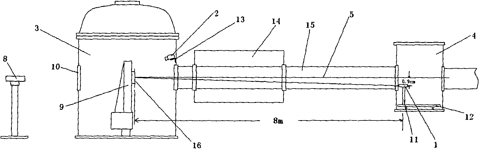
[0025] figure 1 It shows a schematic structural view of a laser plus CCD collimation and positioning device of the present invention, as can be seen from the figure, the device includes a large target chamber 3, a small target chamber 4, a T3 target chamber 14, a laser 1, a CCD2, and a large The sample holder 9 in the target chamber 3, in the present invention, the laser 1 is installed in the small target chamber 4, fixed on the optical platform 12 by the laser installation bracket 11; CCD2 is installed on the entrance of the large target chamber 3 by the CCD bracket 13 above; the T3 target chamber 14 is located between the large target chamber 3 and the small target chamber 4, between the large target chamber 3 and the T3 target chamber 14, and between the T3 target chamber 14 and the small target chamber 4 through the beam duct 15 r...


PUM


Abstract

The invention discloses a laser and CCD (Charge-coupled Device) alignment positioning device and a method thereof. The device comprises a large target chamber, a small target chamber and a T3 target chamber. The large target chamber and the T3 target chamber are connected through a beam pipeline. The T3 target chamber and the small target chamber are connected through the beam pipeline. The large target chamber is provided with a sample rack. An alignment telescope is provided behind the large target chamber. The device is provided with a laser and a CCD simultaneously. The laser is installed in the small target chamber in a mode of fixed eccentricity. The CCD is installed above an inlet of the large target chamber through a CCD rack. With combination use of the laser and the CCD, a centring operation is more accurate, a visual angle position deviation problem in individually using the CCD is solved; since a laser brightness adjust function is added, a laser point can be easily viewed even brightness of the large target chamber is different. By using the laser and CCD alignment positioning device in the invention to carry out alignment positioning, an electric translation stage is avoided, a fault incidence rate is decreased, disadvantages of large position deviation and the like caused by complex machinery structure and angle in a previous laser centring method are overcame.

Description

technical field [0001] The invention belongs to the technical field of accelerator irradiation experiment application devices, and in particular relates to a laser plus CDD collimation positioning device and method. Background technique [0002] Before the accelerator experiment, the irradiation position of the irradiated sample needs to be determined in advance. At present, the commonly used methods include collimating telescope alignment method, CCD monitoring alignment method, laser beam alignment method, etc. The collimating telescope method is to place a collimating telescope outside the irradiation target room along the beam line. It is necessary to correct the position, direction, angle, etc. of the collimating telescope according to the calibrated marks in advance, and then the radiation can be treated The sample is centered. Although this method can directly and accurately determine the irradiation position of the sample to be irradiated, since it is observed from...

Claims


Application Information

Patent Timeline
Patent Type & Authority Applications(China)
IPC IPC(8): G21K5/00
Inventor 郭刚史淑廷陈泉沈东军惠宁刘建成
Owner CHINA INSTITUTE OF ATOMIC ENERGY
Why Eureka
Try Eureka