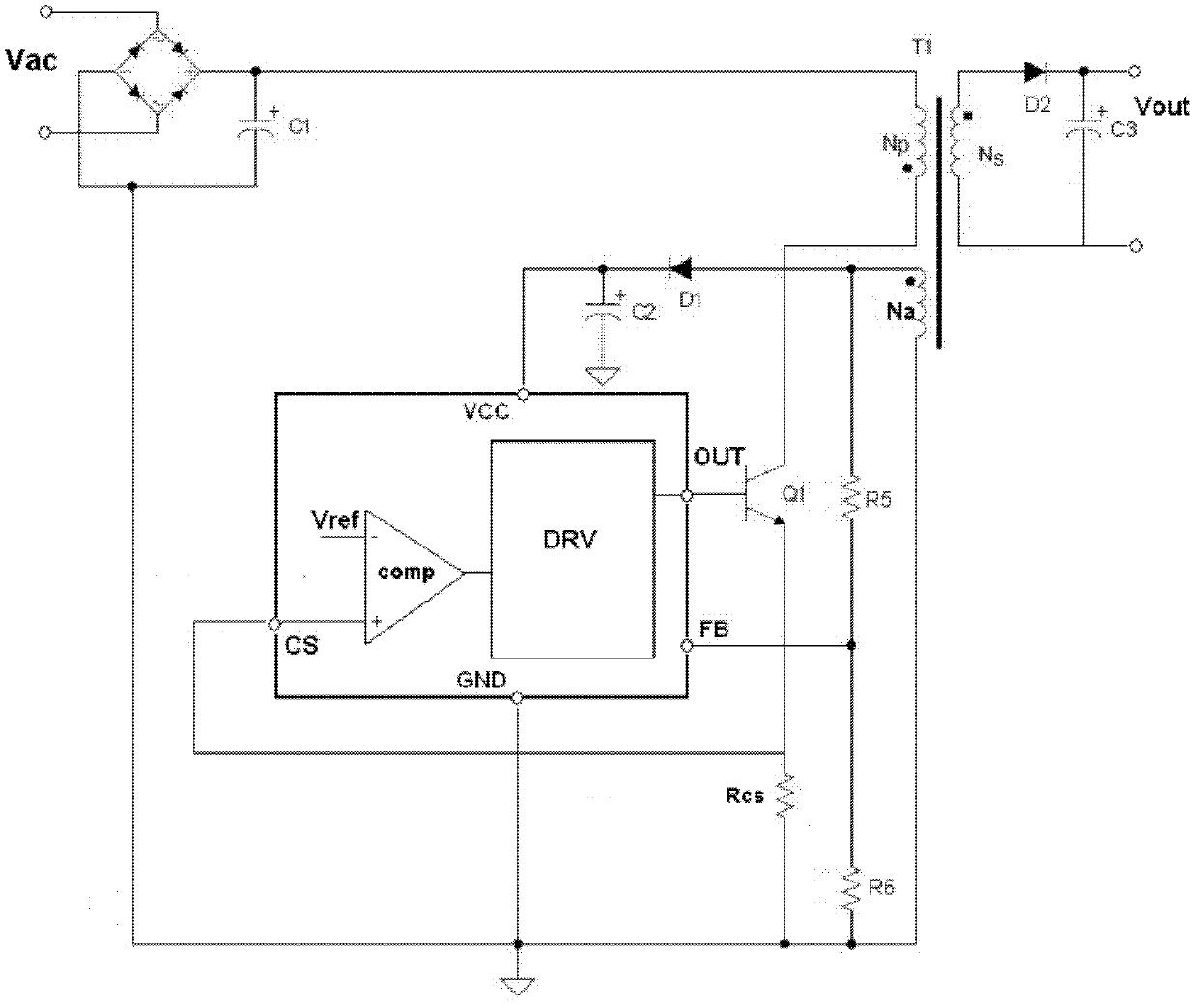
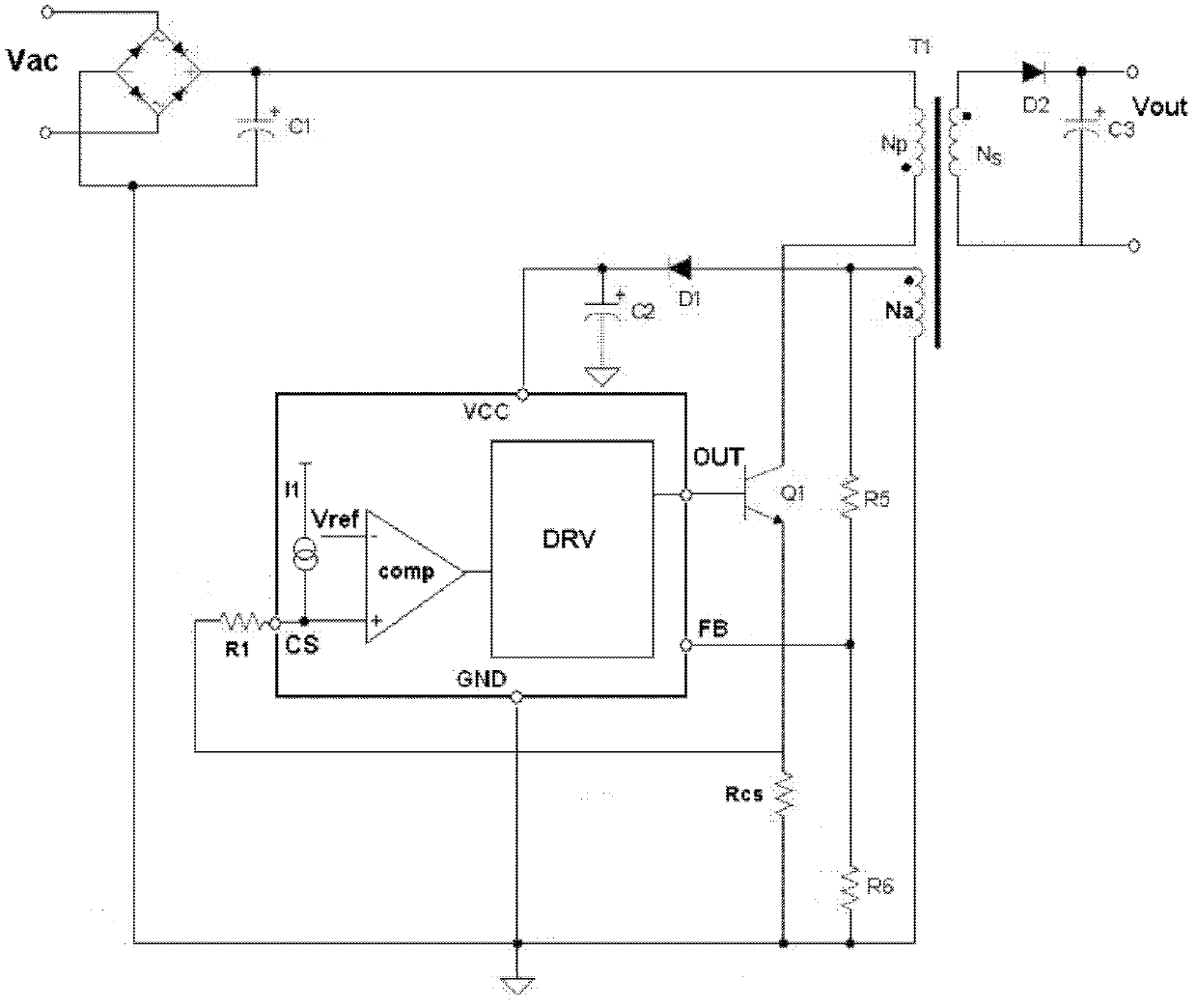
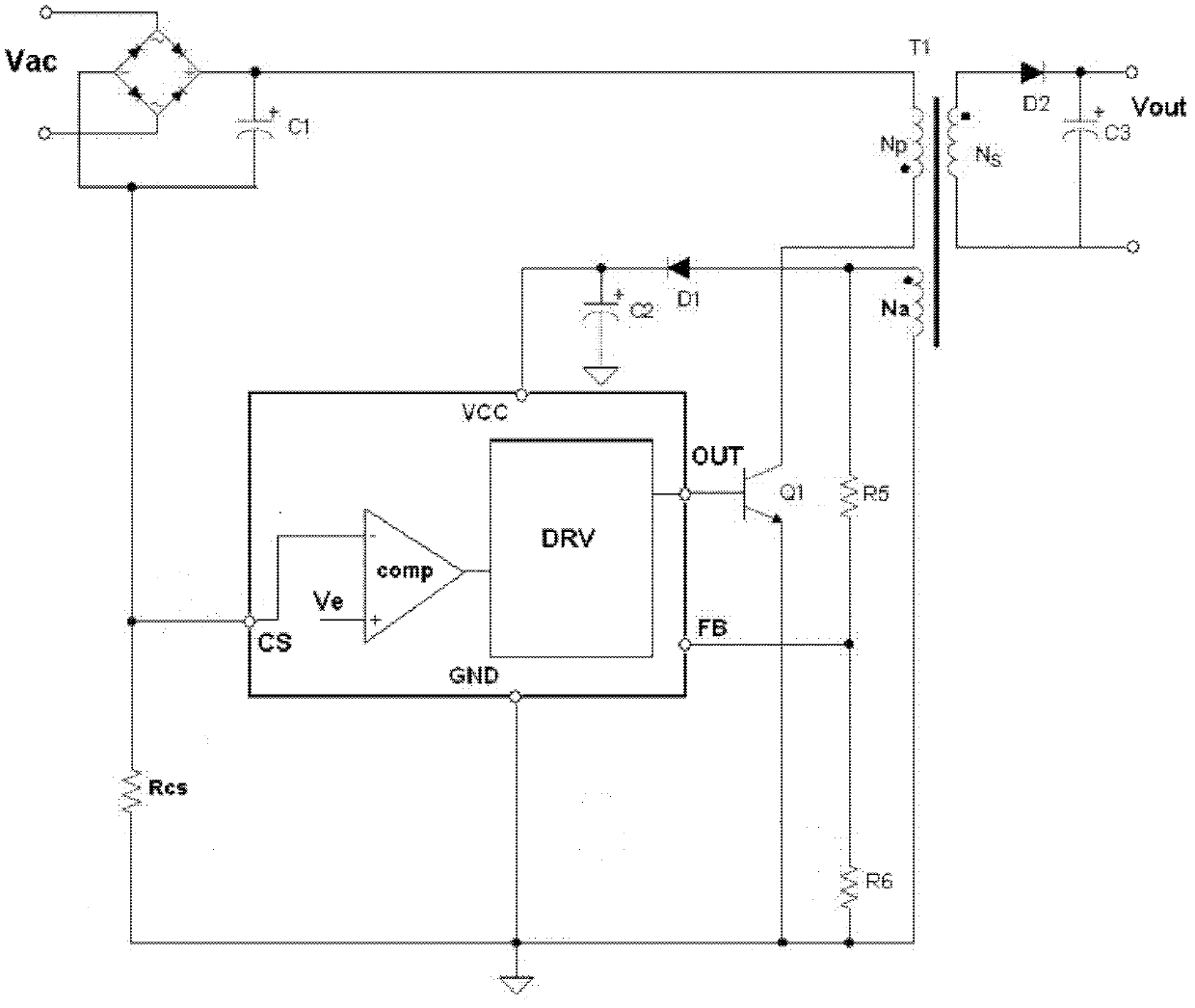
Voltage compensation circuit of switch power line
A line voltage compensation, switching power supply technology, applied in the direction of electrical components, regulating electrical variables, output power conversion devices, etc., can solve the problems of difficult implementation of negative voltage comparison circuits and line voltage compensation circuits, to avoid implementation difficulties and solve problems. Effects that are difficult to achieve with negative currents
- Summary
- Abstract
- Description
- Claims
- Application Information
AI Technical Summary
Problems solved by technology
Method used
Image
Examples
Embodiment 1
[0050] refer to Figure 5 , Figure 5 It is an implementation mode of the switching power supply line voltage compensation circuit provided by the present invention. Among them, the compensation resistor is R1, and the line voltage feedback module is the second resistor R2 whose two ends are respectively connected to the CS terminal and the FB terminal of the primary side controller. The second resistor R2 is an external resistor, and its resistance value can be adjusted conveniently. . Voltage conversion modules include:
[0051] One end is connected to the internal power supply Vdd of the primary side controller, and the other end is connected to the third resistor R3 connected to the comp input end of the voltage comparator;
[0052] One end is connected to the common end of the third resistor R3 and the voltage comparator comp, and the other end is connected to the fourth resistor R4 connected to the CS end of the primary side controller.
[0053] In the switching powe...
Embodiment 2
[0072] refer to Image 6 , Image 6 It is another implementation manner of the switching power supply line voltage compensation circuit provided by the present invention. Wherein, the compensation resistor is R1, and the line voltage feedback module is a second resistor R2 whose two ends are respectively connected to the CS terminal and the FB terminal of the primary-side controller. Voltage conversion modules include:
[0073] One end is connected to the internal power supply Vdd of the primary side controller, and the other end is connected to the current source Ibias of the voltage comparator comp input;
[0074] One end is connected to the common end of the current source Ibias and the voltage comparator comp, and the other end is connected to the fourth resistor R4 connected to the CS end of the primary side controller.
[0075] In the switching power supply line voltage compensation circuit provided by the embodiment of the present invention, the current source Ibias ...
Embodiment 3
[0088] refer to Figure 7 , Figure 7 It is the third implementation mode of the switching power supply line voltage compensation circuit provided by the present invention. Wherein, the compensation resistor is R1, and the line voltage feedback module is a feedback current I3 proportional to the divided voltage Vfb. Voltage conversion modules include:
[0089] One end is connected to the internal power supply Vdd of the primary side controller, and the other end is connected to the third resistor R3 connected to the comp input end of the voltage comparator;
[0090] One end is connected to the common end of the third resistor R3 and the voltage comparator comp, and the other end is connected to the fourth resistor R4 connected to the CS end of the primary side controller.
[0091] In the switching power supply line voltage compensation circuit provided by the embodiment of the present invention, the voltage conversion module divides the third resistor R3 and the fourth resist...
PUM
 Abstract
Description
Claims
Application Information
 - R&D
- Intellectual Property
- Life Sciences
- Materials
- Tech Scout
- Unparalleled Data Quality
- Higher Quality Content
- 60% Fewer Hallucinations
Browse by: Latest US Patents, China's latest patents, Technical Efficacy Thesaurus, Application Domain, Technology Topic, Popular Technical Reports.
© 2025 PatSnap. All rights reserved.Legal|Privacy policy|Modern Slavery Act Transparency Statement|Sitemap|About US| Contact US: help@patsnap.com


