Drive components, surgical instrument systems and surgical robots

A technology of driving components and surgical instruments, which is applied in the field of medical equipment, can solve the problems of electrical signal transmission life loss, limited volume space, worn conductors, etc., and achieve the effects of reducing difficulty and cost, increasing overall size, and reducing cost of use

Active Publication Date: 2022-07-01
SHANGHAI MICROPORT MEDBOT (GRP) CO LTD
View PDF7 Cites 0 Cited by
  • Summary
  • Abstract
  • Description
  • Claims
  • Application Information

AI Technical Summary

Problems solved by technology

[0004] Some existing surgical instruments add a force-sensing detection component at the end of the instrument, but the forceps at the end of the instrument have many degrees of freedom and the volume space is very limited (the diameter of the end of the instrument is usually less than 10mm). It is extremely difficult to arrange force sensing components
At the same time, since the surgical instruments must undergo strict disinfection treatment before each use, the disinfection environment can easily damage the force detection components at the clamp head
These factors lead to a sharp increase in the processing cost of this type of force-sensing surgical instrument, and the service life is very short
For this reason, in some existing design schemes, the force-sensing detection component is installed on the transmission component to detect the force on the end of the instrument, but the electrical signal of the force on the end of the instrument acquired by the force-sensing detection component needs to be transmitted through a conductor. The relative movement between the end parts of the device will wear the conductor, causing electrical signal transmission to induce reliability problems due to the life loss of the conductor, and also increase the cost of clinical use

Method used


Image

  • Drive components, surgical instrument systems and surgical robots
  • Drive components, surgical instrument systems and surgical robots
  • Drive components, surgical instrument systems and surgical robots

Examples


Embodiment Construction

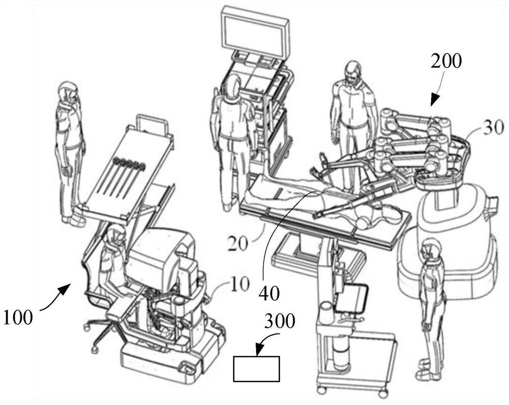
[0056] In order to make the content of the present invention clearer and easier to understand, the present invention will be further described below with reference to the accompanying drawings and embodiments of the description. However, it can be understood that the present invention is not limited to the specific embodiments described below, and general substitutions well known to those skilled in the art are also covered within the protection scope of the present invention. It should be noted that, the accompanying drawings are all in a very simplified form and in inaccurate scales, and are only used to facilitate and clearly assist the purpose of explaining the embodiments of the present invention.

[0057] It should be understood that, in the following description, reference to "on" and "under" various components may be made based on the drawings. Spatial terms such as "under", "under", "below", "above", etc., are used for the purpose of easily describing the positional r...


PUM


Abstract

The invention relates to a drive assembly, a surgical instrument system and a surgical robot; the surgical robot includes a mechanical arm and a surgical instrument system, the surgical instrument system includes a surgical instrument and a drive assembly, the surgical instrument includes an end effector, the end of the mechanical arm and the surgical instrument system connection; the drive assembly includes a housing, a drive module, a measurement module and a fixing flange; the drive module includes a drive motor and a drive shaft; the drive motor is accommodated in the housing; the drive motor is used to drive the end effector to move through the drive shaft; the fixing method The flange is connected to the drive shaft, and the fixed flange and the drive shaft are kept relatively stationary in the circumferential direction; the measurement module is used to obtain the rotational variation of the fixed flange, so as to obtain the output torque of the drive motor according to the rotational variation of the fixed flange, and then Get the force on the end effector. The invention improves the accuracy of end force detection, and also reduces the difficulty and cost of force detection.

Description

technical field [0001] The invention relates to the technical field of medical instruments, in particular to a drive assembly, a surgical instrument system and a surgical robot. Background technique [0002] Minimal invasive surgery refers to the surgical operation performed by doctors using modern medical equipment such as abdomen and thoracoscope as well as supporting instruments. Compared with open surgery, minimally invasive surgery has many advantages, such as less trauma, less bleeding, and faster recovery. It has been more and more widely used in clinical surgery. In recent years, with the development of science and technology and the improvement of medical needs, the laparoscopic surgical robot used to assist in the realization of minimally invasive surgery has emerged and has developed rapidly. Modern medical equipment that integrates a large system. [0003] The emergence of laparoscopic surgical robots has overcome many shortcomings of traditional micro-invasive...

Claims


Application Information

Patent Timeline
Patent Type & Authority Patents(China)
IPC IPC(8): A61B34/30A61B50/31H02K7/10
CPCA61B34/30A61B50/31A61B34/76H02K7/10A61B2050/311A61B2034/301
Inventor 朱祥何裕源何超
Owner SHANGHAI MICROPORT MEDBOT (GRP) CO LTD
Why Eureka
Try Eureka