automatic horizontal stretcher
A stretcher and horizontal technology, applied in stretchers, vehicle rescue, medical transportation, etc., can solve the problems of many people, secondary injuries, inconvenient use, etc., and achieve the effect of simple operation and avoiding secondary injuries
- Summary
- Abstract
- Description
- Claims
- Application Information
AI Technical Summary
Problems solved by technology
Method used
Image
Examples
Embodiment 1
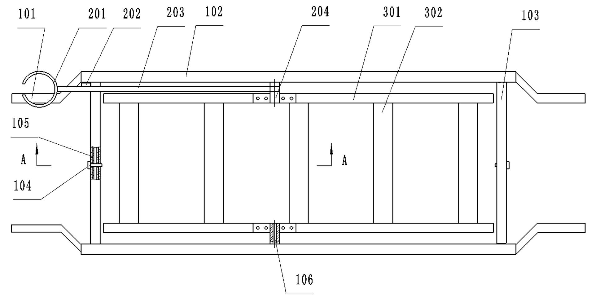
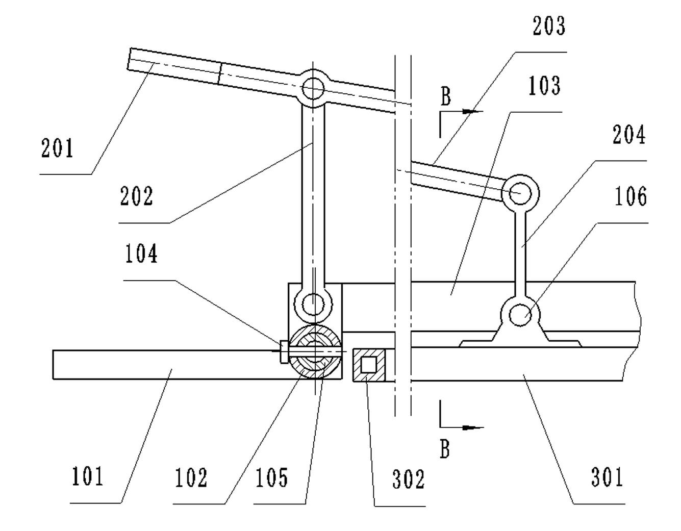
[0024] Embodiment 1: with reference to attached Figure 1~4 , is a structural schematic diagram of Embodiment 1 of the present invention, including an outer frame 1 and an inner frame 3, the outer frame 1 is composed of an outer frame straight beam 103 and an outer frame crossbeam to form a rectangular frame-shaped body, and the longitudinal ends of the rectangular frame-shaped body A stretcher handle 101 is provided, and the outer frame beam is composed of a pair of telescopic outer sleeve 102 and an inner tube 105, and a sleeve locking mechanism is arranged between the outer sleeve 102 and the inner tube 105, and the sleeve locking mechanism is a pin . The inner frame 3 is composed of two inner frame straight beams 301 and several inner frame beams 302 to form a rectangular grid-shaped bed body, and the inner frame 3 is arranged on the inner side of the outer frame 1 . The middle parts of the outer frame 1 and the inner frame 3 are hinged to each other: the inner sides of t...
Embodiment 2
[0025] Embodiment 2: with reference to attached Figure 5 , is a structural schematic diagram of the horizontal adjustment mechanism in Embodiment 2 of the present invention. Compared with Embodiment 1, the difference of this embodiment is that the bushing is divided into two sections, one of which is connected to the crank rod 204 described above, The other section is connected to the inner frame straight beam 301 of the inner frame 3, and the two sections of bushes are engaged in a slit shape and can be separated.
Embodiment 3
[0026] Embodiment 3: with reference to attached Figure 6~Figure 7 , is a schematic structural diagram of the sleeve locking mechanism in Embodiment 3 of the present invention. Compared with Embodiment 1, the difference of this embodiment is that the sleeve locking mechanism has the following structure: a slot is provided on the outer sleeve 102, and The inner tube 105 is provided with a "V"-shaped hook 108, the upper end of the "V"-shaped hook 108 is provided with a return spring 109 and the upper end of the "V"-shaped hook 108 can be stuck in the slot of the outer sleeve 102 Among them, the lower part of the "V"-shaped hook 108 is hinged with each other and the inner side is provided with a pull wire 107. There is no switch button 106 on the stretcher handle 101. The switch button 106 is connected to the pull wire 107 and pulls the pull wire 107, thereby making the "V" The upper end of the shaped hook 108 shrinks inward and withdraws from the said slot.
PUM
 Abstract
Description
Claims
Application Information
 - R&D
- Intellectual Property
- Life Sciences
- Materials
- Tech Scout
- Unparalleled Data Quality
- Higher Quality Content
- 60% Fewer Hallucinations
Browse by: Latest US Patents, China's latest patents, Technical Efficacy Thesaurus, Application Domain, Technology Topic, Popular Technical Reports.
© 2025 PatSnap. All rights reserved.Legal|Privacy policy|Modern Slavery Act Transparency Statement|Sitemap|About US| Contact US: help@patsnap.com


