Centrifugal Acceleration Disc Structure of Pusher Centrifuge

A centrifugal acceleration and centrifuge technology, applied in the field of centrifuges, can solve the problems of small diameter design, small material impact, poor feeding, etc., and achieve the effects of reducing scratches, reducing impact force, and reducing filtration resistance.

Active Publication Date: 2011-12-21
ZHEJIANG QINGJI CENTRIFUGE MFG
View PDF6 Cites 15 Cited by
  • Summary
  • Abstract
  • Description
  • Claims
  • Application Information

AI Technical Summary

Problems solved by technology

[0005] The purpose of the present invention is to solve the problem of reducing the impact of the material on the screen under the state of acceleration change when the pusher centrifuge accelerates the material into the separation state, effectively improving the product integrity rate, reducing the wear of the contact parts, and the solid material feeding. Unsmooth and uneven problems, provide a reasonable structure of the centrifugal acceleration disk structure of the pusher centrifuge, it is an acceleration disk that can accelerate the material smoothly, and its unique turbine blade can help the material to be fed by the screw conveyor or The material supplied by the pipe moves forward along the axial direction, smoothly enters the acceleration disc, and is forced to accelerate by the turbine blades. The diameter design here is small, and the impact on the material is small; due to the drive of the blades, it can ensure that the material and the acceleration disc are synchronized. And the diameter of the blade is close to the inner diameter of the first-stage drum screen, and the material enters the screen in the first-stage drum at almost the same speed, so that the impact force between the material and the screen is close to zero.

Method used


Image

  • Centrifugal Acceleration Disc Structure of Pusher Centrifuge
  • Centrifugal Acceleration Disc Structure of Pusher Centrifuge
  • Centrifugal Acceleration Disc Structure of Pusher Centrifuge

Examples


Embodiment Construction

[0024] The technical solutions of the present invention will be further specifically described below through the embodiments and in conjunction with the accompanying drawings.

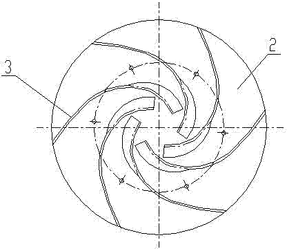
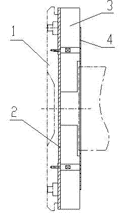
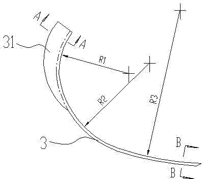
[0025] see figure 2 , the present embodiment is a centrifugal acceleration plate structure of a pusher centrifuge, two large circular flat plates 2 and a small circular flat plate 4 parallel to each other are set, wherein the large circular flat plate 2 is fixed on the pusher plate 1 of the pusher centrifuge On, the small circular flat plate 4 is connected with the large circular flat plate 2 as a whole with a screw rod. Set 6 blades 3 between the large circular flat plate 2 and the small circular flat plate 4, and the 6 blades 3 are distributed into a uniform radial shape, such as figure 1 As shown, the tail ends of the six blades 3 are located on the same circumference, and the curve of the blades 3 is designed as a turbine centrifugal line, which is composed of three arcs, such as image 3 R1, R2...


PUM


Abstract

The invention relates to the technical field of centrifuges, in particular to a centrifugal accelerating disc structure of a push-type centrifuge, and solves the problem that impact force applied to a screen by a material is high when the material is accelerated to enter a separation state by the push-type centrifuge. The structure comprises a large circular flat plate and a small circular flat plate which are parallel to each other, and is characterized in that: a plurality of blades are arranged between the two flat plates and are uniformly and radially distributed; the tail ends of the plurality of blades are positioned on the same circumference; the curve of each blade is a turbine centrifugal line; each blade consists of a plurality of sections of circular arcs; the radii of the plurality of sections of circular arcs of each blade are gradually increased from the head to the tail end; and a section of part on the head of each blade is provided with a radial arc surface which inclines to the rotation direction of each blade. The structure greatly reduces the scratch, wear and defect of crystal grains in the material, ensures that the material is fed smoothly and uniformly, canreduce the residual moisture content of the separated material, and can effectively separate a material which is difficult to separate.

Description

technical field [0001] The invention relates to the technical field of centrifuges, in particular to a centrifugal acceleration disc structure of a pusher centrifuge in a material supply distribution system for suspension materials to be separated. Background technique [0002] The pusher centrifuge is a high-efficiency filter centrifuge with continuous operation. The separated suspension needs to be continuously fed into the centrifuge through the feed pipe, accelerated by the feed distributor, and evenly sprinkled in the first stage drum. . The solid part is trapped on the screen to form a ring-shaped filter cake. The first-stage drum, which is both rotating and reciprocating, pushes this part of the filter cake forward along the axial direction of the drum for a certain distance during the return journey. When it is located on the sieve vacated by the filter cake, the subsequent incoming materials form a new filter cake. With the reciprocating movement of the first-stag...

Claims


Application Information

Patent Timeline
Patent Type & Authority Applications(China)
IPC IPC(8): B04B11/02B04B3/02
Inventor 沙恩典陆斌
Owner ZHEJIANG QINGJI CENTRIFUGE MFG
Why Eureka
Try Eureka