
A collimating mechanism for a convexity meter

A technology of convexity meter and collimation, applied in the field of nuclear technology application

Inactive Publication Date: 2011-12-21
TSINGHUA UNIV
View PDF7 Cites 9 Cited by
  • Summary
  • Abstract
  • Description
  • Claims
  • Application Information

AI Technical Summary

Problems solved by technology

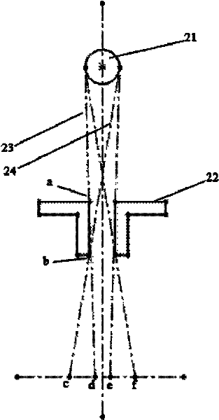
The problem caused by the non-ideal point source of the target point is that after the beam emitted by the circular target point is collimated, three areas will be formed behind the collimator, the shielding area, the penumbra area and the total shadow area

Method used


Image

  • A collimating mechanism for a convexity meter
  • A collimating mechanism for a convexity meter
  • A collimating mechanism for a convexity meter

Examples


Embodiment

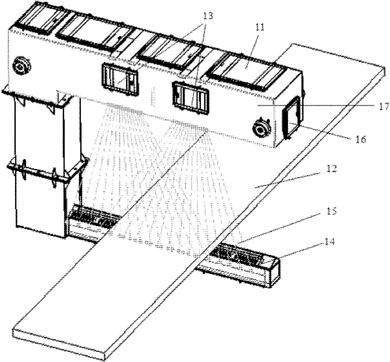
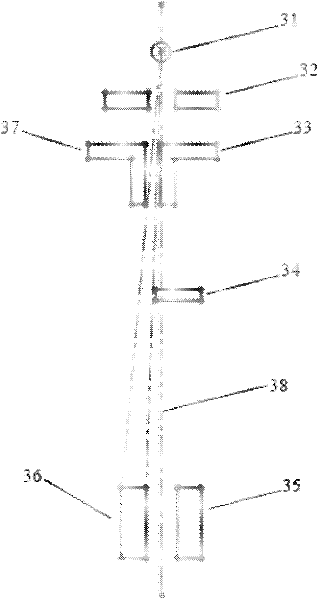
[0023] The convexity meter targeted by the present invention uses two sets of radiation source-detector array combinations, such as figure 1 As shown, the direction perpendicular to the upper arm end surface 16 of the C-shaped frame is the X direction, and the direction perpendicular to the side surface 17 of the C-shaped frame is the Y direction. In the X direction as image 3 As shown in the figure, two X-ray machines are spaced apart in the same linear direction in the X direction, the detector arrays are arranged along the X direction, and the two rows of detector arrays 35 and 36 are parallel.

[0024] The X-ray beam emitted by the X-ray machine is an elliptical cone beam, the long axis is along the X direction, and the short axis is along the Y direction, and the angle is 90°×30°. Also in the X and Y directions, the solid angle of the detector array relative to the X-ray machine is 45°×0.34°, such as image 3 As shown, in the Y direction, the distance between the two rows of...


PUM


Abstract

The invention relates to a collimation mechanism for a convexity meter, and belongs to the field of nuclear technology application. The collimation mechanism includes two sets of collimation devices with the same structure, and each set of collimation devices includes 3-stage collimators, and the collimators from the first stage to the third stage are arranged sequentially along the radiation direction of a radiation source. The first-level collimator includes a first tungsten plate; the second-level collimator includes second to fifth tungsten plates, two mounting plates, a bottom plate, a flat plate, and a fixing block, and the two mounting plates are placed on the flat plate, The two mounting plates are respectively connected with the second to the fifth tungsten plates, the two mounting plates are connected with the flat plate, the two mounting plates are connected, the flat plate is connected with the bottom plate, and a spring is pressed between the flat plate and the fixed block; the third level collimation The device includes the sixth tungsten plate, and the sixth tungsten plate is fixed by the top wire; after this three-level collimation, the ray beam emitted by the ray source becomes a collimated ray beam, which solves the problem that the convexity instrument lacks the collimation function for the ray beam emitted by the ray source Problems, improve the accuracy of product detection.

Description

Technical field [0001] The invention belongs to the field of nuclear technology application, and particularly relates to a collimating mechanism for a crown tester for detecting steel strips in steel rolling production lines in steel mills. Background technique [0002] The convexity meter is a key equipment for the production and control of steel strips, which can instantaneously and continuously measure the thickness distribution of the cross-section of the steel strip. The structure of the convexity meter, such as figure 1 As shown, the main structure is a C-shaped frame 11, the steel strip 12 to be tested passes between the upper and lower arms of the C-shaped frame, the ray source 13 is located inside the upper arm of the C-shaped frame, and the ray source is two X-ray machines, two X-ray machines The optical machines are identical and are placed at a distance; the ray detector 14 is located inside the lower arm of the C-shaped frame and contains two rows of detector arrays....

Claims


Application Information

Patent Timeline
IPC IPC(8): B21B38/04G01B15/02
Inventor 吴志芳李立涛张玉爱邢桂来王振涛
Owner TSINGHUA UNIV
Learn More