foam pump

A foam pump and foam technology, which is applied in the field of foam pumps, can solve the problems of high cost and achieve the effect of preventing spring rust and uniform foam

Inactive Publication Date: 2011-12-21
DERXIN SHANGHAI COSMETICS
View PDF4 Cites 15 Cited by
  • Summary
  • Abstract
  • Description
  • Claims
  • Application Information

AI Technical Summary

Problems solved by technology

[0002] The existing foam pump is composed of a suction cylinder and a suction liquid cylinder whose outlets are connected. The suction cylinder is composed of a cylinder body and a piston. When in use, press the pressure head to make the piston of the suction cylinder and the p

Method used


Image

  • foam pump
  • foam pump
  • foam pump

Examples


Embodiment 1

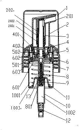
[0051] Such as figure 1 The presence of the present invention is a cord, attached image 3 Example 1 network management structure diagram, attachment Figure 5 The decomposition and attachment of the present invention Figure 4 It is shown in the structure diagram of the embodiment 1 cylinder, large piston, main column, connection rod, and small piston connection.

[0052] A foam pump is used to absorb the liquid in the container and spray the foam from the nozzle of the liquid.Large piston 6, rotation cover 7, connection rod 8, small piston 9, cylinder 10, spring and valve 12, there are network tube 3 in the head 2 and the air valve 4, the spring is set outside the main column 5, of which:

[0053]One presses 2, with a nozzle 201 bubble spray, 2 sets of heads to take over 202 lower parts 2021, with ring grooves or card slots in the inner wall of the 2021 diameter.A ring -shaped convex steps 2022 at the beginning of 2021;

[0054] One network tube 3, extend from below to push the pip...

Embodiment 2

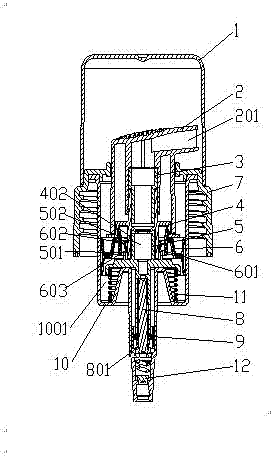
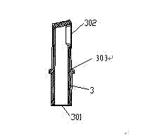
[0073] Such as figure 2 Another working status of the present invention embodiment 2 and attachment Figure 7 Example 2 The structure diagram of the network tube, other structures are the same or similar as the embodiment 1. The foam pump is composed of the head, the car cover, and the cylinder.Large piston 6, rotation cover 7, connection rod 8, small piston 9, cylinder 10, large spring 11, valve 12 and small spring 13, with network tube at the head 2 and gas valve 4, the second spring is located in the main columnIn addition to the air room of the cylinder 10, of which:

[0074] One presses 2, with a nozzle 201 bubble spray, 2 sets of heads to take over 202 lower parts 2021, with ring grooves or card slots in the inner wall of the 2021 diameter.A ring -shaped convex steps 2022 at the beginning of 2021;

[0075] One network tube 3 ', extended from below to take over 202, the lower end of the network management 3' is a coarse filter 301 ', the upper end is a fine filter 302', and th...


PUM


Abstract

The invention relates to a foam pump, which is used to absorb liquid in a container and make the liquid spray out foam from a nozzle. The shell is composed of a pressure head, a screw cap and a cylinder. The shell includes a pressure head, an air valve, a main column, Large piston, screw cap, connecting rod, small piston, cylinder, spring and valve. There is a network pipe between the pressure head and the air valve, and the spring is provided between the main column and the base of the cylinder. Among them: a network pipe extends into the pressure head sleeve from below Inside, the lower end of the network pipe communicates with the air valve, and at least a filter screen is provided at the entrance of the network pipe; the air valve is a tubular structure, and the middle part is provided with a circular ring with a downward peripheral edge and a convex edge, and the pressure head is against the top of the circular ring. An air inlet groove is arranged on the inner wall of the ring, and an exhaust groove is arranged on the inner wall of the tube below the air valve. Because the spring is placed in the air chamber of the cylinder, it prevents it from contacting with chemical materials and prevents the spring from rusting; and because the large and small pistons can be unlinked, it provides sealing, and the design of the network tube makes the sprayed foam more uniform.

Description

Technical field [0001] The invention involves a foam pump. Background technique [0002] The existing foam pump is composed of the export -connected vapor cylinder and the solution cylinder. Among them, the pumping cylinder is composed of the cylinder body and the piston.The piston is connected. When using the pressure head, press the piston piston in the pumping cylinder synchronously with the piston of the pumping cylinder.The mixing becomes a bubble, but this constitution is high. [0003] In addition, the patent number ZL2005200636954 revealed another type of foam pump, including the cylinder body, head, plug tube, and spring.The center and cylinder are located on the periphery of the liquid cylinder. The cylinder is matched with the ring wing of the lower head.The liquid inlet of the lower part of the section and the liquid cylinder constitutes the inlet valve inlet. The lower part of the limited pillar is provided with inverted hooks to hook the inlet of the inlet.The liqui...

Claims


Application Information

Patent Timeline
IPC IPC(8): B65D47/34B65D83/00
CPCB05B11/1087B05B11/1025
Inventor 王雅灿
Owner DERXIN SHANGHAI COSMETICS
Why Eureka
Try Eureka