
Hydraulic jacking device and method of using the same

A jacking device and hydraulic technology, which is applied in the direction of lifting devices, lifting frames, etc., can solve the problems of difficult transfer of heavy-tonnage tower workpieces, and achieve the effects of reducing manufacturing and transportation costs and being easy to use

Inactive Publication Date: 2011-12-21
王勇
View PDF5 Cites 6 Cited by
  • Summary
  • Abstract
  • Description
  • Claims
  • Application Information

AI Technical Summary

Problems solved by technology

[0003] The present invention provides a hydraulic jacking device and its use method, which overcomes the above-mentioned deficiencies in the prior art, and can effectively solve the problem of difficult transfer of heavy-tonnage tower workpieces

Method used


Image

  • Hydraulic jacking device and method of using the same
  • Hydraulic jacking device and method of using the same
  • Hydraulic jacking device and method of using the same

Examples


Embodiment 1

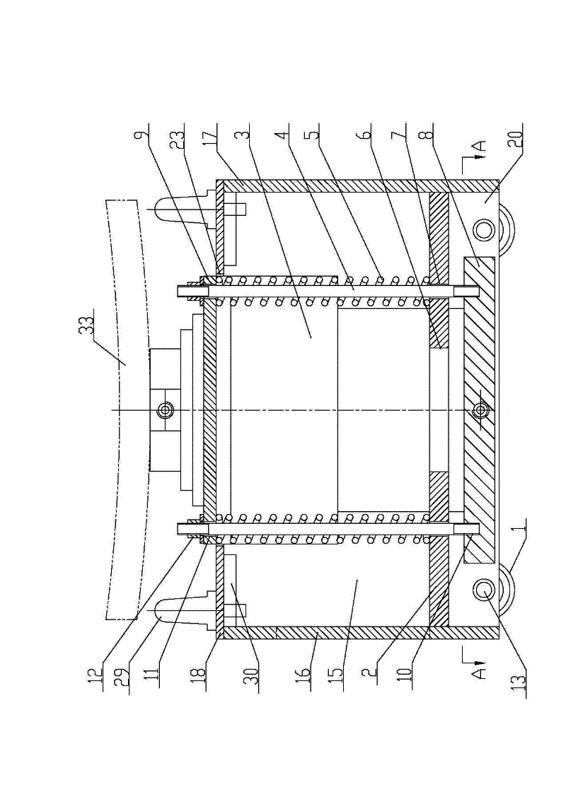
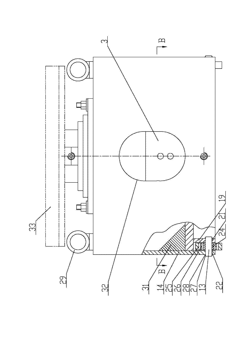
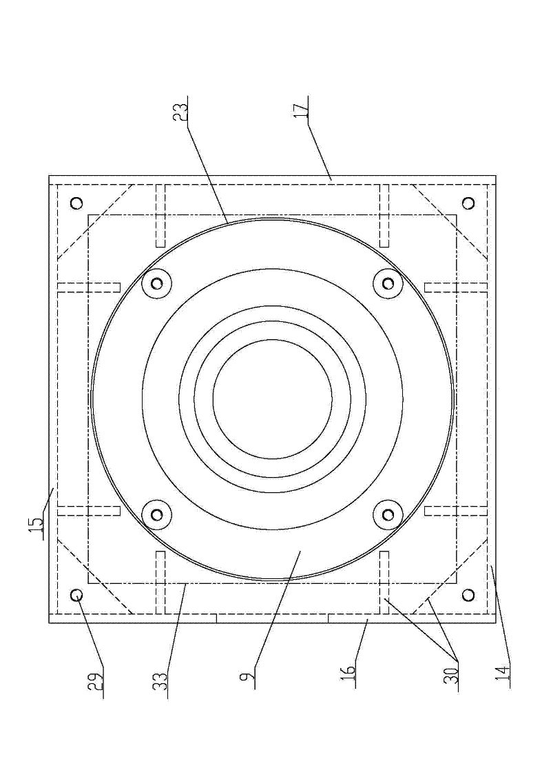
[0024] Embodiment 1: as attached figure 1 , 2 , 3, the hydraulic jacking device includes a box, a roller 1, a supporting plate 2, a hydraulic cylinder 3, a support rod 4 and a compression spring 5; the bottom of the box is equipped with a roller 1, and the inner cavity of the box is fixed with The supporting plate 2 has a supporting plate cylinder hole 6 in the middle of the supporting plate 2, and there are connecting rod through holes 7 on the supporting plate 2 around the supporting plate cylinder hole 6; The piston rod of the heavy object, the cylinder body top of the hydraulic cylinder 3 has a hydraulic cylinder flange 9, the cylinder body lower end of the hydraulic cylinder 3 is fixed with a hydraulic cylinder seat plate 8, and the hydraulic cylinder 3 bottom is sleeved in the supporting plate cylinder hole 6 and can Moving down, the hydraulic cylinder base plate 8 is located in the inner cavity of the box below the supporting plate 2, and the support rod 4 is fixedly i...

Embodiment 2

[0034] Embodiment 2: A method of using a hydraulic jacking device: first, the hydraulic jacking device is pushed to the bottom of the tower tube workpiece through the roller 1, and the hydraulic cylinder 3 is filled with oil by controlling the hydraulic valve, and the piston rod at the upper end of the hydraulic cylinder 3 Move and make the upper part of the arc-shaped top plate 33 fully contact with the lower end of the tower workpiece; then, the piston rod continues to move up and bear the gravity of the tower workpiece, and the reaction force of the tower workpiece to the piston rod of the hydraulic cylinder 3 makes the hydraulic cylinder 3 and the hydraulic cylinder The flange 9 moves down and compresses the compression spring 5, and the hydraulic cylinder 3 drives the hydraulic cylinder seat plate 8 to move down together through the support rod 4 until the hydraulic cylinder seat plate 8 fully touches the ground. Then, control the hydraulic valve so that the hydraulic cyli...


PUM


Abstract

The invention relates to the technical field of hoisting equipment, in particular to a hydraulic hoisting device and a using method thereof. The hydraulic hoisting device comprises a case body, a roller, a support plate, a hydraulic cylinder, a support rod and a compression spring, wherein the lower part of the case body is provided with the roller; the support plate is fixed in the inner cavity of the case body; a support plate cylinder hole is formed in the middle of the support plate; a connecting rod through hole is formed in the support plate around the support plate cylinder hole; the upper part of the hydraulic cylinder is provided with a piston rod which can be extended upwards to the upper side of the case body and support heavy objects; the upper part of the cylinder body of thehydraulic cylinder is provided with a hydraulic cylinder flange; and the lower end of the cylinder body of the hydraulic cylinder is fixedly provided with a hydraulic cylinder base plate. The hydraulic hoisting device is convenient to use; by the using method, heavy-tonnage tower barrel workpieces can be effectively transferred; when supported by the compression spring, the hydraulic cylinder canbe away from the ground and freely moved along with the case body; when loaded, the hydraulic cylinder falls down and compresses the compression spring; and the hydraulic cylinder base plate is supported on the ground to make the roller and the case body not stressed. The hydraulic hoisting device has the characteristics of saving labor, along with high efficiency, is safe, simple and convenient and greatly lowers manufacturing cost and transportation cost.

Description

technical field [0001] The invention relates to the technical field of lifting equipment, and relates to a hydraulic jacking device and a method for using the same. Background technique [0002] With the rapid development of the wind power industry, the installed capacity of domestic wind turbines has grown from 750 kilowatts and 1500 kilowatts to 2.5 megawatts and 3 megawatts. And began to develop 10 MW units. The popularity of megawatt-class large-capacity wind turbines has increased the length, diameter, and thickness of steel plates used in wind turbine towers, and due to the long blade length of megawatt-class large-capacity wind turbines, the yield strength of the tower And load requirements are getting higher and higher, and changes in the material and plate thickness used in the tower have also led to the continuous increase in the weight of the tower. At present, the production and manufacturing of towers are generally carried out in the factory building. During t...

Claims


Application Information

Patent Timeline
Patent Type & Authority Applications(China)
IPC IPC(8): B66F7/18B66F7/28
Inventor 周晓明王克王勇张雪江徐成春张勇武迎峰
Owner 王勇
Learn More