

Self-resetting metal damper
A metal damper, self-resetting technology, applied in the direction of building components, anti-vibration, etc., can solve the problems of residual deformation of metal dampers, unfavorable building performance requirements, non-structural components and adverse effects of human living environment, etc., to reduce residual deformation, Simple and reliable structure, the effect of dissipating vibration energy
- Summary
- Abstract
- Description
- Claims
- Application Information
AI Technical Summary
Problems solved by technology
Method used
Image

Examples
Embodiment 1
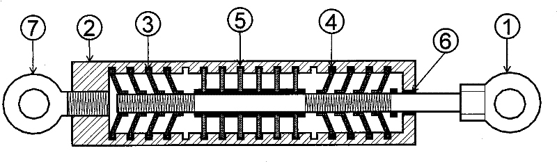
[0026] figure 1 It is a schematic diagram of the structure of this embodiment. This embodiment is composed of a piston rod 1, a housing 2, a disc spring 3 with threads, a disc spring 4 with reverse threads, an energy dissipation sheet 5, a sealing body 6, and a connecting screw 7. When assembling, the shell 2 is divided into two halves along the axis, and the disc springs 3 and 4 and the energy dissipation sheet 5 are assembled on the piston rod 1 in a certain order, and the distance between the disc springs 3 and 4 can be adjusted by threads, and then Put the assembled piston rod 1 into the tooth groove 12 of the casing 2, re-weld the casing 2 as a whole, and install the sealing body 6 and the connecting screw 7. Then the piston rod 1 is rotated in the axial direction. Due to the existence of a pair of reverse threads, the relative position of the piston rod 1 will not change, but preload is applied to the disc springs 3 and 4. The size of the preload can be adjusted accord...
Embodiment 2
[0033] Figure 7 It is the specific structure schematic diagram of this embodiment. It includes a shell 16 and a disc spring 17 without thread. In this embodiment, the disc springs 17 are arranged in series and have a relatively large deformation capacity. The preload is applied by Belleville springs 3 and 4 with positive and negative threads. Other structures are the same as in Embodiment 1. Disc springs 3 and 4 are connected in series with the remaining disc springs 17 and apply a preload to it.
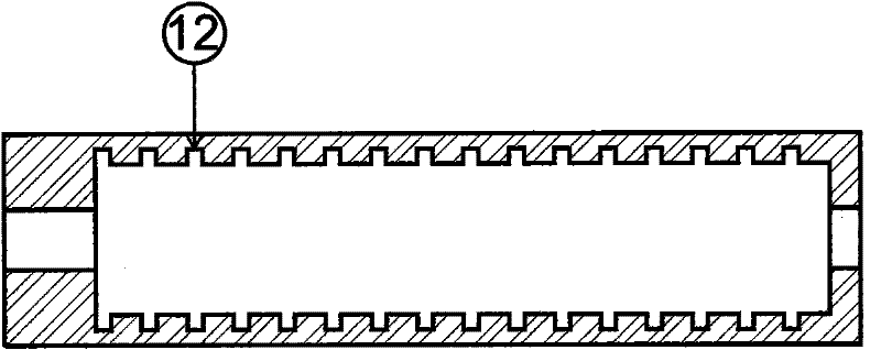
[0034] Figure 8 is a sectional view of the housing of this embodiment. A toothed groove 12 is provided in the middle of the casing for fixing the energy dissipation sheet, and slide grooves 18 are provided near the two ends for placing disc springs 17 without threads.
Embodiment 3
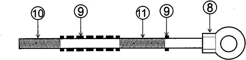
[0036] refer to Figure 9-11 , The self-resetting metal damper of this embodiment includes a housing 19, a prestressed cable 20, sliders 21 and 22 with positive and negative threads, and a pin key 23. Other structures are basically the same as in Embodiment 1. Among them, the prestressed cable 20 is made of polymer material, which has the characteristics of high strength and strong deformability. During implementation, the slide blocks 21, 22 and the energy dissipation sheet 5 are installed on the piston rod 1, and one end of the prestressed cable 20 is anchored in the pin hole 28 of the slide blocks 21 and 22, and the assembled piston rod 1 Put it into the casing 19, and combine the casing 19 into a whole. The other end of the prestressing cable 20 is drawn out from the key hole 24 of the housing 19 and anchored. Finally, the piston rod 1 is rotated in the axial direction, and the reverse thread drives the sliders 21 and 22 to move centripetally, applying a pre-tension forc...
PUM
 Abstract
Description
Claims
Application Information