
Shield machine with center drilling system

A shield machine and drive system technology, applied in the field of shield machines, can solve problems such as low tunneling resistance and poor cutting effect at the center of the shield machine, and achieve the goal of improving tunneling resistance, reducing tool wear, and enhancing cutting strength Effect

Inactive Publication Date: 2011-12-21
王茂
View PDF5 Cites 31 Cited by
  • Summary
  • Abstract
  • Description
  • Claims
  • Application Information

AI Technical Summary

Problems solved by technology

[0003] The invention provides a shield machine with a center drilling system, which solves the problems of poor cutting effect at the center part of the shield machine and low ability to overcome tunneling resistance

Method used


Image

  • Shield machine with center drilling system
  • Shield machine with center drilling system
  • Shield machine with center drilling system

Examples


Embodiment Construction

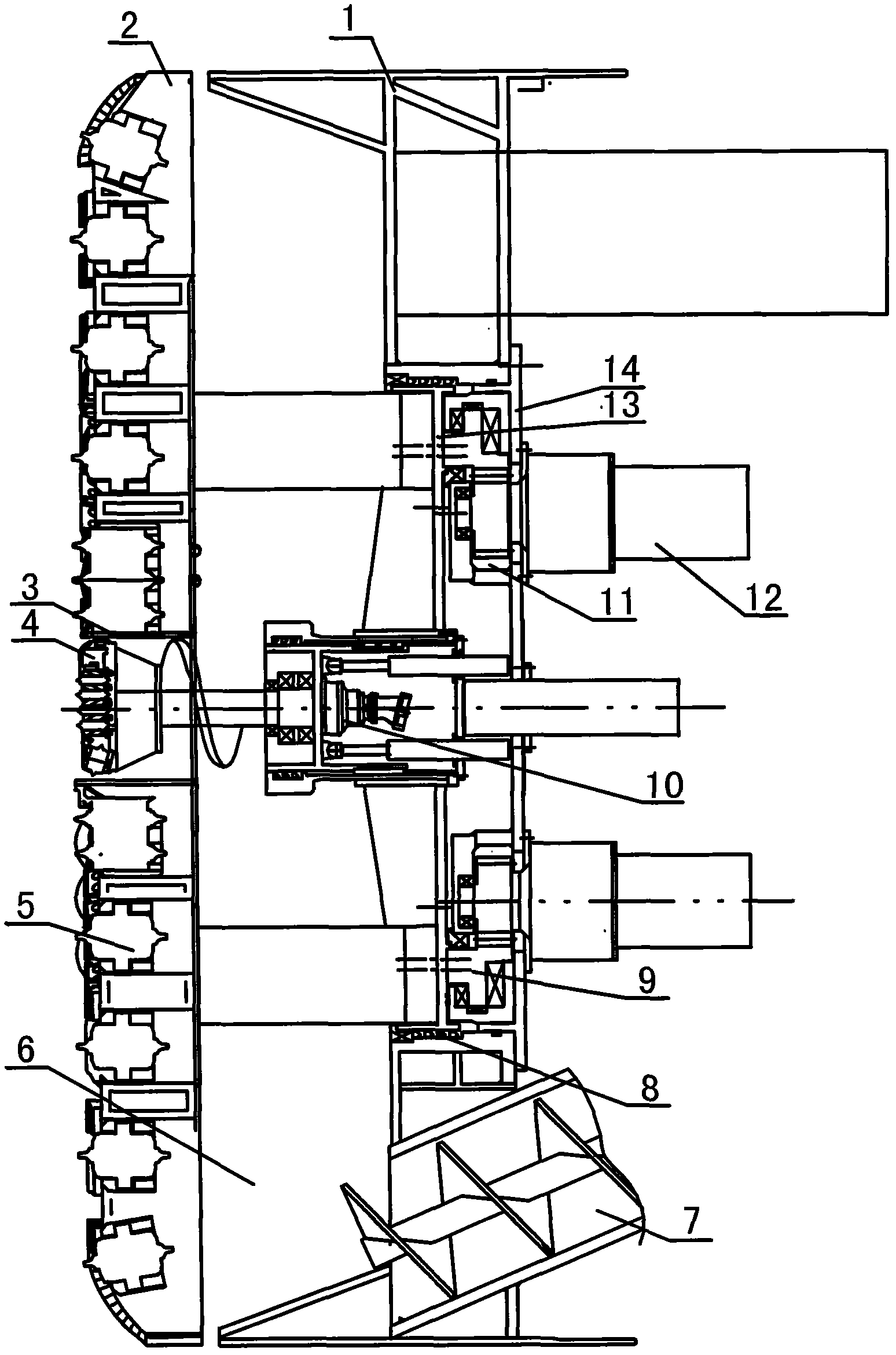
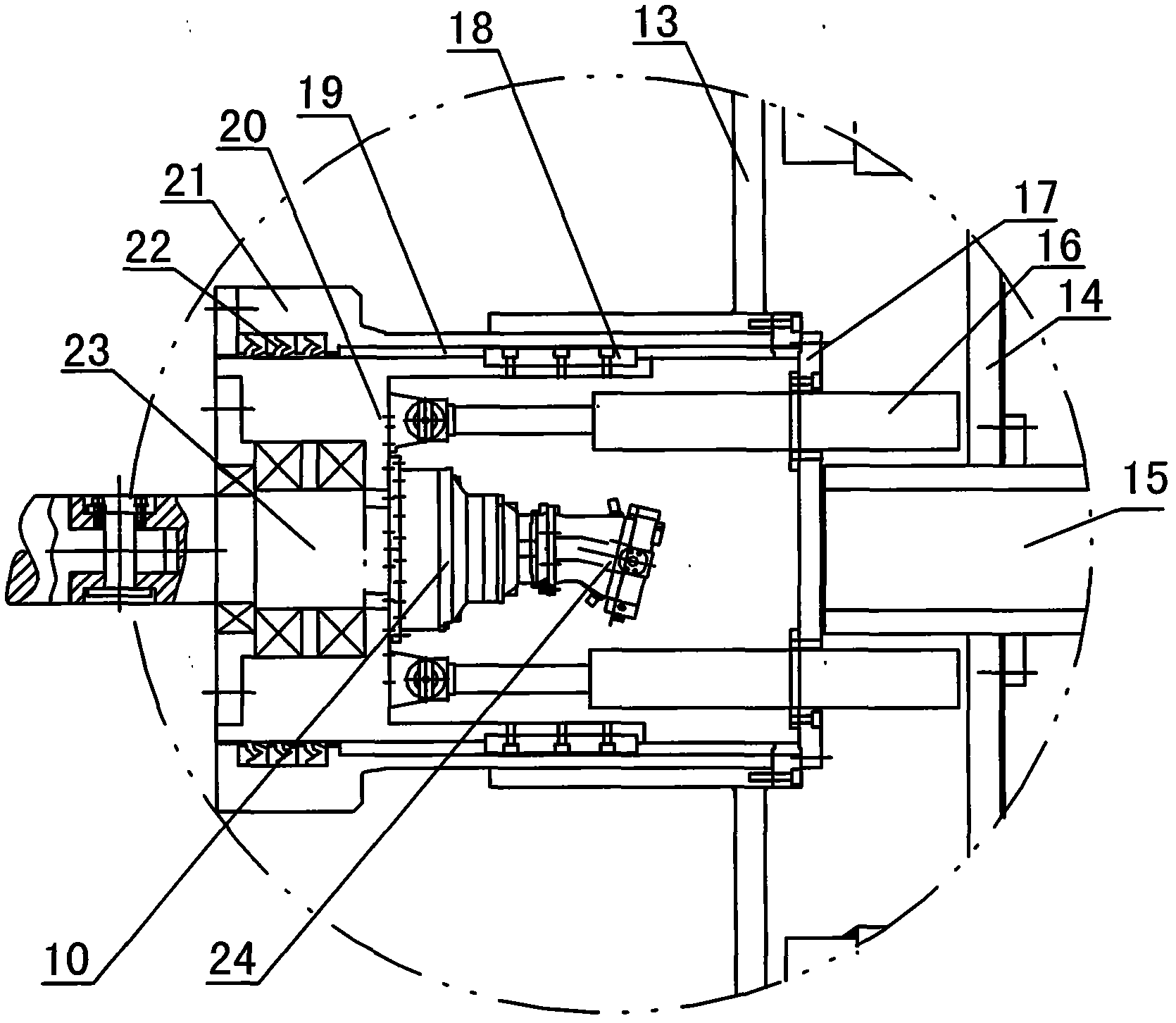
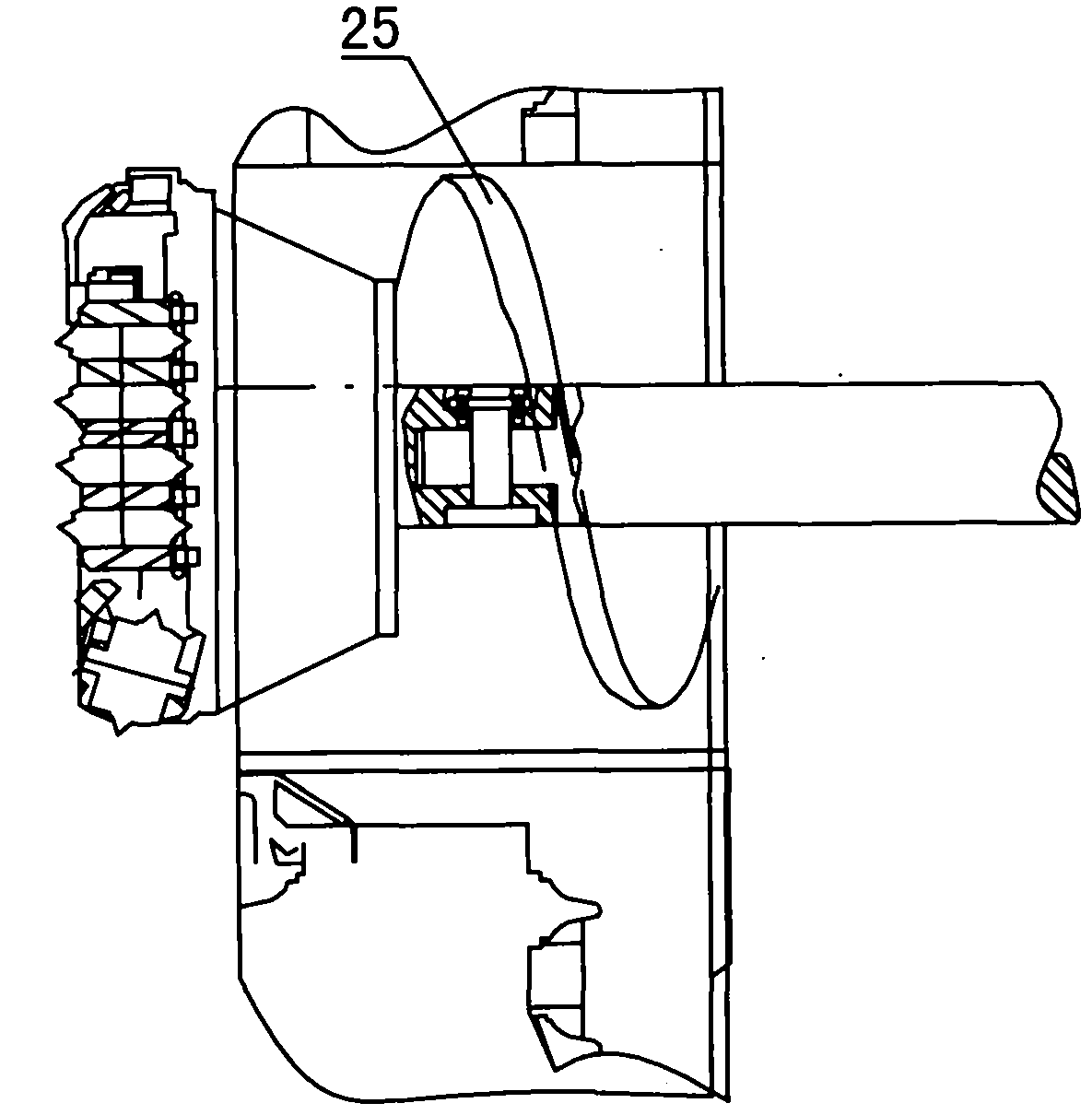
[0017] like Figures 1 to 4 As shown, a specific embodiment of the present invention is given. In the figure, a shield machine with a center drilling system includes a front shield shell 1, a main cutter head 2, a center outlet 3 for cutting rock and soil at the soil bin, a hydraulic pressure Rotary joint 15, the hob 5 on the main cutter head 2, the soil bin 6, the screw conveyor 7 for conveying the cut rock and soil, the sealing system 8 of the shield machine, the reduction box 10, the main drive 12, and the support of the main bearing Disc 14, etc., a small cutter head 4 is installed in the center of the main cutter head 2, and small hobs are installed on it. The number and size of the small hobs can vary according to the soil conditions. The small cutter head 4 is used as the center drilling system. The cutting part is installed on the top of the transmission shaft 23 of the central drilling mechanism, the fixed part of the hydraulic rotary joint 15 is connected with the ce...


PUM


Abstract

The invention discloses a shield machine with a center drill system. The shield machine comprises a front shield shell, a main cutter, a soil bin, a cutting rock soil outlet, a spiral conveyer, a sealing system, and a driving system; the center drill system is arranged in the center of the main cutter of the shield machine and comprises a center drill mechanism and the driving system; the center drill mechanism comprises a cutting part, a transmission shaft, an inner sleeve and an outer sleeve; the cutting part comprises a small cutter which is arranged in the center of the main cutter; the transmission shaft and a bearing are arranged in the inner sleeve of a center drill; the inner sleeve is connected with the outer sleeve through a key; the driving system comprises a pushing system and a rotation system; the pushing system consists of a hydraulic cylinder which is fixed on a shell end plate; and a hydraumatic rotation adapter of the shield machine is connected with the shell end plate of the center drill system. The center drill system is arranged on the shield machine, so that the cutting force of the center part of the cutter of the shield machine is enhanced, the tunneling resistance overcoming capacity of the shield machine is improved, energy sources are saved, and operation efficiency is improved.

Description

technical field [0001] The invention relates to a shield machine, in particular to a shield machine with a center drilling system. Background technique [0002] Due to the low linear speed of the center part of the traditional shield machine, the cutting effect of the center part is poor, especially when encountering geological conditions such as hard rock and hard soil, it is easy to cause tool wear and mud cake phenomenon, which increases the tunneling resistance of the shield machine , or even unable to move forward, causing job delays. Contents of the invention [0003] The invention provides a shield machine with a center drilling system, which solves the problems of poor cutting effect at the center part of the shield machine and low ability to overcome tunneling resistance. [0004] In order to achieve the above purpose, the following technical solutions are adopted: [0005] A shield machine with a center drilling system, including a front shield shell, a main cu...

Claims


Application Information

Patent Timeline
IPC IPC(8): E21D9/08
Inventor 王茂
Owner 王茂
Features
  • Generate Ideas
  • Intellectual Property
  • Life Sciences
  • Materials
  • Tech Scout
  • Unparalleled Data Quality
  • Higher Quality Content
  • 60% Fewer Hallucinations
Learn More