
Multi-purpose high-efficiency pneumatic liquid pump

A high-efficiency technology of air pressure liquid, applied in the direction of liquid variable volume machinery, pump, piston pump, etc., can solve the problems of backflow, low water output efficiency, etc., and achieve the effect of large flow water output and high lift

Inactive Publication Date: 2011-12-21
石家庄联合盛鑫泵业有限公司
View PDF8 Cites 8 Cited by
  • Summary
  • Abstract
  • Description
  • Claims
  • Application Information

AI Technical Summary

Problems solved by technology

[0005] (3) There is no check valve installed on the water outlet pipe, the water going out will flow back when the water enters the tank, and the water outlet efficiency is too low

Method used


Image

  • Multi-purpose high-efficiency pneumatic liquid pump
  • Multi-purpose high-efficiency pneumatic liquid pump
  • Multi-purpose high-efficiency pneumatic liquid pump

Examples


Embodiment 1

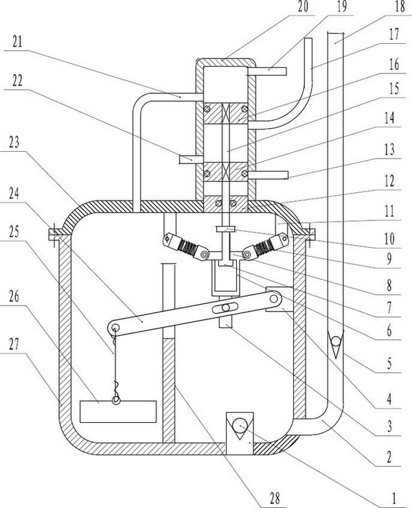
[0025] see figure 1 and figure 2 , which is a small air-driven liquid pump with intermittent water discharge from a single pump. In this embodiment, the lower intake and exhaust pipe 22 and the lower exhaust pipe 13 of the two-position five-way valve are blocked.

[0026] This embodiment includes a main pump, a two-position five-way valve, a float mechanism and a valve stem booster mechanism; the main pump includes a main pump body 27 and a main pump cover 23, and a device is installed There is the water inlet pipe of the main pump water inlet check valve 1, and the main pump outlet connecting pipe 2 equipped with the main pump outlet water check valve 5 is arranged at the lower end of the side wall of the main pump body 27, and the upper end of the main pump outlet connecting pipe 2 Equipped with an outlet pipe 18;

[0027] The two-position five-way valve includes a valve body 20, a lower valve cover 12, a valve stem 15 equipped with an upper piston 16 and a lower piston ...

Embodiment 2

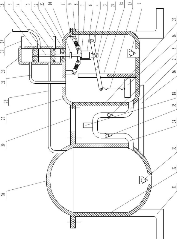
[0034] See attached image 3, which connect the left and right sides of the main and auxiliary pumps, and complete continuous water pumping. The difference between this embodiment and Embodiment 1 is that it also includes an auxiliary pump. The auxiliary pump includes an auxiliary pump body 32 and an auxiliary pump cover 30. On the bottom of the auxiliary pump body 32, there is a water stop for the auxiliary pump. The water inlet pipe of the return valve 33 is provided with an auxiliary pump outlet connecting pipe 34 equipped with an auxiliary pump outlet check valve 35 at the lower end of the side wall of the auxiliary pump body 32. The auxiliary pump outlet connecting pipe 34 and the main pump outlet connecting pipe 2 Connect with the outlet pipe 18 through a tee;

[0035] The lower intake and exhaust port of the two-position five-way valve communicates with the cavity of the auxiliary pump through the lower intake and exhaust pipe 22, and the lower exhaust pipe 13 is insta...

Embodiment 3

[0041] See attached Figure 4 , the main and auxiliary pumps are connected in parallel up and down, which is suitable for deep wells and continuous water pumping.

[0042] The difference between embodiment 3 and embodiment 2 is that the auxiliary pump is connected up and down with the main pump through the connecting plate 37 , and the working process of embodiment 3 is the same as that of embodiment 2.


PUM


Abstract

The invention relates to a multi-purpose pneumatic liquid pump which comprises a main pump, a two-position five-way valve, a float mechanism and a valve stem boosting mechanism, wherein the two-position five-way valve is communicated with the main pump cavity through an upper intake-exhaust pipe; the valve stem boosting mechanism is composed of a pair of spring supports, a pair of spring support seats, a guiding frame and a guiding frame seat; the float mechanism comprises a float, a lever, a lever guide plate and a lever support. The multi-purpose efficient pneumatic liquid pump provided by the invention also comprises an auxiliary pump, wherein an outlet connecting pipe of the auxiliary pump and an outlet connecting pipe of the main pump are connected with a water outlet pipe through a three-way valve; the two-position five-way valve is communicated with the auxiliary pump cavity through a lower intake-exhaust pipe. The invention has the following advantages: the pump can realize high-lift high-flow water yield and constant pumping; the pump can not only be used to pump water in deep wells, rivers, lakes and reservoirs for field irrigation, but also be applied to the transportation of crude oil, chemical liquids and flammable and combustible liquids, as well as urban sewage discharge.

Description

technical field [0001] The invention relates to a multi-purpose high-efficiency pneumatic liquid pump, which is not only suitable for pumping water from deep wells, rivers, lakes and reservoirs for farmland irrigation, but also suitable for the transportation of crude oil, chemical liquids and inflammable and explosive liquids. Discharge of urban sewage. Background technique [0002] The Chinese patent discloses a "self-spraying air pressure automatic pumping machine" (patent application number: 200510043206.3), which includes a box body with water inlet and outlet, air inlet and outlet, and an adjustment mechanism, which is characterized in that the adjustment mechanism includes a floating ball and On the suspension body connected with it, the upper end of the floating ball is provided with an exhaust port valve plug, and its lower end is provided with an air inlet valve plug matched with the air duct, and the exhaust port is provided with a pipeline communicating with the ...

Claims


Application Information

Patent Timeline
IPC IPC(8): F04B9/12
Inventor 张家政张利张旗
Owner 石家庄联合盛鑫泵业有限公司
Features
  • Generate Ideas
  • Intellectual Property
  • Life Sciences
  • Materials
  • Tech Scout
  • Unparalleled Data Quality
  • Higher Quality Content
  • 60% Fewer Hallucinations
Learn More