Hydraulic follow-up rotating mechanism

A slewing mechanism and follow-up technology, which is applied in the direction of fluid pressure actuators, mechanical equipment, servo motors, etc., can solve difficulties, limit the output power and application range of hydraulic follow-up slewing mechanisms, and cannot realize high output torque of slewing mechanisms, etc. problem, to achieve the effect of wide range of use and simple structure

Inactive Publication Date: 2014-04-02
泸州天府液压件有限公司
View PDF7 Cites 0 Cited by
  • Summary
  • Abstract
  • Description
  • Claims
  • Application Information

AI Technical Summary

Problems solved by technology

[0002] The hydraulic follow-up slewing mechanism is widely used in various construction machinery, such as graders, which drive the scraper to rotate through the hydraulic follow-up slewing mechanism to achieve the purpose of leveling the road surface; the hydraulic follow-up slewing mechanism widely used at present mainly includes There are two types, one is the follow-up slewing mechanism driven by the hydraulic motor. Its disadvantage is that the slewing mechanism cannot output large torque, because the torque of this mechanism is determined by the flow rate and flow of the hydraulic motor. When it reaches a certain level, It will be very difficult to increase the flow rate and flow rate, which will limit the output power and application range of the hydraulic follow-up slewing mechanism; The mandrel, the pinion gear set on the mandrel through the structure for transmitting torque, and a double-acting cylinder whose bottom is hinged to the frame, the piston rod of the double-acting cylinder is hinged to one end of the connecting rod, and the other end of the connecting rod is connected to the mandrel The small gear meshes with the large gear through the structure of the transmission torque; the mechanism alternately supplies oil to the rod chamber and the rodless chamber of the double-acting cylinder, and the piston rod and the connecting rod drive the small gear and the large gear to rotate , can realize the forward and reverse rotation of the large gear, and then the large gear is connected with the executive part to realize the rotary motion; but the large gear can only swing forward and reverse within a certain angle range, and cannot realize the continuous rotation of 360°, which is Because when the piston rod pushes the pinion to rotate through the connecting rod, when the piston rod and the connecting rod coincide on a straight line, the piston rod cannot push the connecting rod to rotate around the mandrel at the other end. There are two dead point positions in one circle, and the 360° continuous rotation of the actuator cannot be realized by using this mechanism, which will also limit the application range of the hydraulic follow-up slewing mechanism; if two double-acting cylinders are used to push two pinions respectively To drive the large gear to rotate, a complex automated electrical system is often required to alternately and orderly supply or discharge oil to the two oil ports of the two double-acting cylinders, resulting in a complex structure and high cost of the control device

Method used


Image

  • Hydraulic follow-up rotating mechanism
  • Hydraulic follow-up rotating mechanism
  • Hydraulic follow-up rotating mechanism

Examples


Embodiment Construction

[0022] The present invention will be described in further detail below in conjunction with the accompanying drawings.

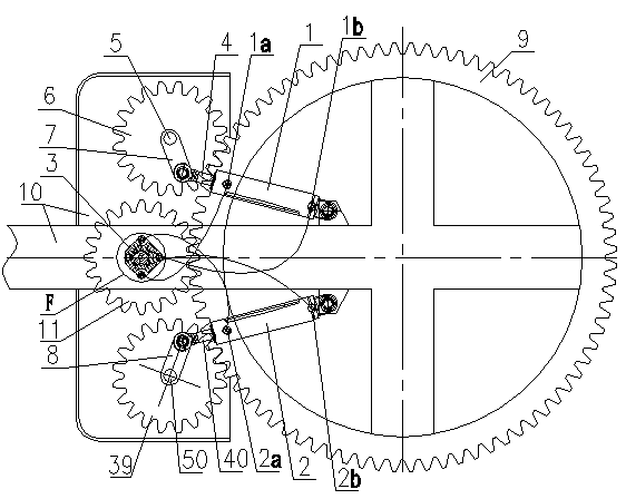
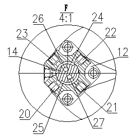
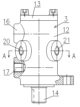
[0023] like figure 1 As shown, the hydraulic follow-up slewing mechanism includes a fixed frame 10, two mandrels 5 and 50 arranged on the frame 10 through bearings, and a structure that can transmit torque through keys or welding is arranged on each mandrel. The pinion 6 or 39 on the 5 or 50, the two double-acting oil cylinders 1 and 2 hinged with the frame 10 at the bottom, and the fixed rotary valve 3, the piston rods 4 or 40 of the two double-acting oil cylinders 1 and 2 It is hinged with one end of the corresponding connecting rod 7 or 8, and the other end of each connecting rod 7, 8 is connected with the corresponding mandrel 5 or 50 by welding, and the two small gears 6, 39 are meshed with the large gear 9 , the large gear 9 is also meshed with a follower gear 11, such as Figure 2 to Figure 11 As shown, the rotary valve 3 includes a valve body 12, a ...


PUM


Abstract

The invention discloses a hydraulic follow-up rotating mechanism, which comprises a machine frame, two central shafts arranged on the machine frame, small gears on all the central shafts, two double-acting oil cylinders hinged with the machine frame, and a rotating valve, wherein a piston rod of each double-acting oil cylinder is hinged with one end of a respectively corresponding connecting rod; the other end of each connecting rod is connected with a respectively corresponding central shaft; the two small gears are engaged with a large gear; the large gear is engaged with a follow-up gear; the rotating valve comprises a valve body, a valve cover, a valve core and a sealing ring which is arranged on the valve core; an oil inlet, an oil outlet and four working oil ports are formed in the valve body; and two working oil ports which are formed at the periphery of the valve body at intervals are connected with a rod-containing cavity oil port or a rod-free cavity oil port of a respective double-acting oil cylinder through pipelines respectively. The sequences of oil supply or oil discharge at the rod-containing cavity oil ports or the rod-free cavity oil ports of the two double-acting oil cylinders are adjusted through the rotating valve, so that the rotating mechanism can be continuously rotated in the positive and reverse directions at the angle of 360 DEG and output high torque, and has the advantages of simple structure and wide using range.

Description

technical field [0001] The invention relates to a hydraulic follow-up rotary mechanism. Background technique [0002] The hydraulic follow-up slewing mechanism is widely used in various construction machinery, such as graders, which drive the scraper to rotate through the hydraulic follow-up slewing mechanism to achieve the purpose of leveling the road surface; the hydraulic follow-up slewing mechanism widely used at present mainly includes There are two types, one is the follow-up slewing mechanism driven by the hydraulic motor. Its disadvantage is that the slewing mechanism cannot output large torque, because the torque of this mechanism is determined by the flow rate and flow of the hydraulic motor. When it reaches a certain level, It will be very difficult to increase the flow rate and flow rate, which will limit the output power and application range of the hydraulic follow-up slewing mechanism; The mandrel, the pinion gear set on the mandrel through the structure f...

Claims


Application Information

Patent Timeline
Patent Type & Authority Patents(China)
IPC IPC(8): F15B9/14
Inventor 王利陈斌
Owner 泸州天府液压件有限公司
Why Eureka
Try Eureka