Optical filter, optical filter module, and photometric analyzer

a technology of optical filter and optical filter module, which is applied in the field of optical filter, optical filter module, and photometric analyzer, can solve the problems of reducing the spectroscopic accuracy of the optical filter, unable to ensure the flatness of the optical film surface, etc., and achieves the effect of accurate spectroscopic characteristics and high accuracy

Inactive Publication Date: 2014-09-30
SEIKO EPSON CORP
View PDF6 Cites 4 Cited by
  • Summary
  • Abstract
  • Description
  • Claims
  • Application Information

AI Technical Summary

Benefits of technology

[0017]According to the configuration, the above described filter and the optical filter module including the light receiving unit are provided, and measurement of the amount of li

Problems solved by technology

However, in the tunable interference filter having the above described configuration, as the gap between optical films is made smaller by an external force, the substrates are deformed in the parts in which the optical films are formed and flat

Method used


Image

  • Optical filter, optical filter module, and photometric analyzer
  • Optical filter, optical filter module, and photometric analyzer
  • Optical filter, optical filter module, and photometric analyzer

Examples


first embodiment

Advantages of First Embodiment

[0071]According to the first embodiment, there are the following advantages.

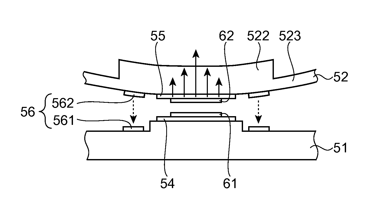
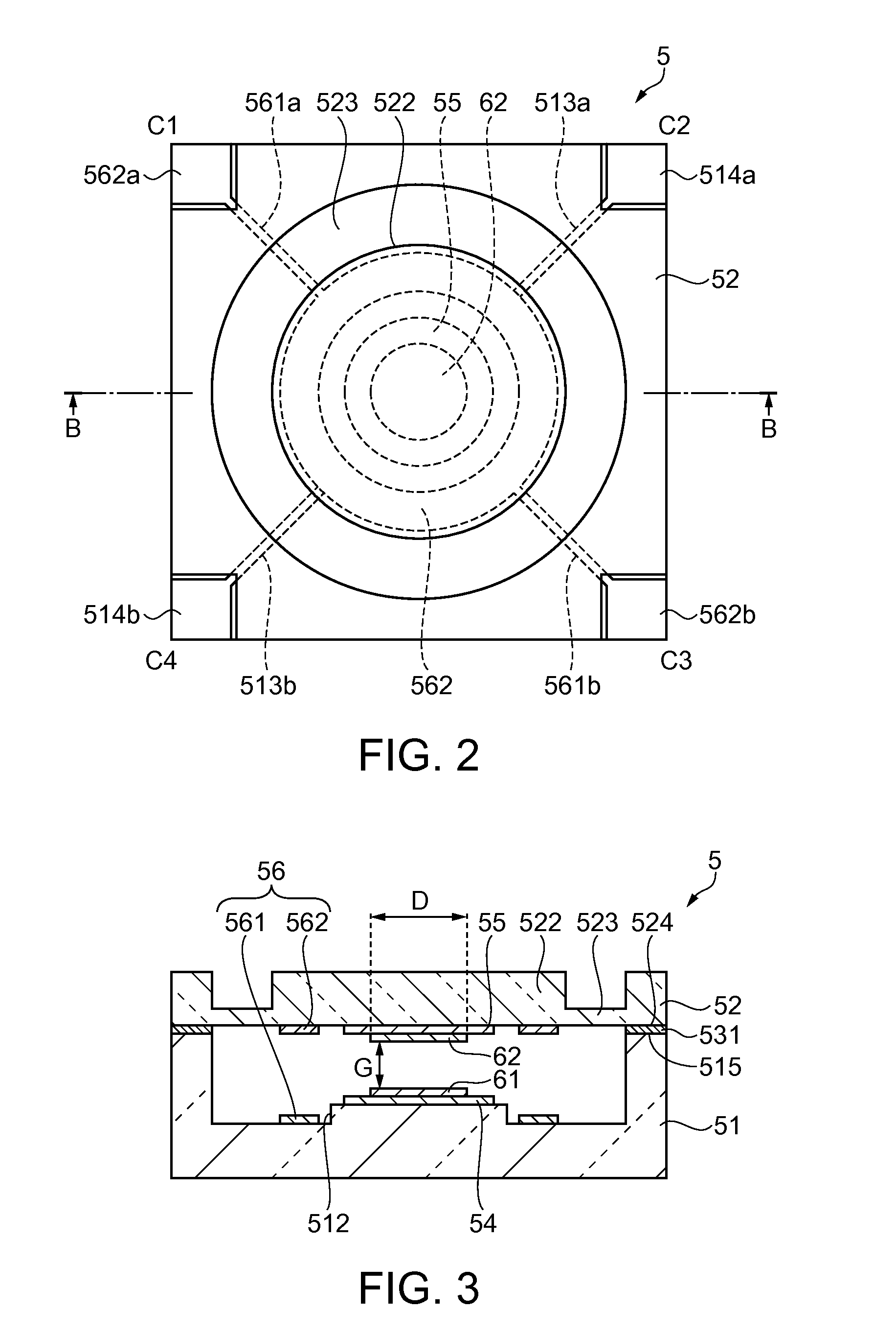
[0072]In the etalon 5 according to the embodiment, the opposed first charged body film 61 and second charged body film 62 are charged with the same polarity, and the Coulomb force acts between them and becomes the repulsive force for the force that deforms the movable substrate 52. In this manner, the deformation of the movable part 522 produced by the driving of the electrostatic actuator 56 may be suppressed, flatness of the first optical film 54 and the second optical film 55 may be kept, and a uniform gap without variations may be ensured within the surfaces of the optical films. Thus, the spectroscopic accuracy of the etalon 5 can be improved.

[0073]Further, in the etalon 5, the first charged body film 61 and the second charged body film 62 having light transmissivity are formed in the optical paths of the respective optical films 54, 55, deformation of the movable substrate...

modified examples of embodiment

[0077]Next, a modified example of the etalon in the first embodiment will be explained.

[0078]FIG. 5 is a schematic sectional view showing a modified example of the etalon. In the modified example, the configurations of the optical films and the charged body films are different from those of the etalon of the first embodiment. The same component elements as those of the etalon of the first embodiment have the same signs and their explanation will be omitted.

[0079]The first optical film 54 is formed on the fixed substrate 51 of an etalon 8, and a first charged body film 63 is formed on the first optical film 54. The first charged body film 63 is formed in the same size as that of the first optical film 54. The second optical film 55 is formed in the movable part 522 of the movable substrate 52, and a second charged body film 64 is formed on the second optical film 55. The second charged body film 64 is formed in the same size as that of the second optical film 55. Further, the first c...

second embodiment

[0087]As below, an example of the gas detector will be explained according to the drawings.

[0088]FIG. 7 is a schematic view showing an example of the gas detector including the etalon.

[0089]FIG. 8 is a block diagram showing a configuration of a control system of the gas detector in FIG. 7.

[0090]The gas detector 100 includes a sensor chip 110, a channel 120 having a suction port 120A, a suction channel 120B, an eject channel 120C, and an eject port 120D, and a main body part 130 as shown in FIG. 7.

[0091]The main body part 130 includes a detection unit (optical filter module) including a sensor part cover 131 having an opening to which the channel 120 is detachably attached, an ejecting unit 133, a housing 134, an optical unit 135, a filter 136, the etalon (tunable interference filter) 5, a light receiving device 137 (light receiving unit), etc., a control unit 138 that processes a detected signal and controls the detection unit, a power supply unit 139 that supplies power, etc. Furth...


PUM


Abstract

An optical filter includes a first substrate, a second substrate opposed to the first substrate, a first optical film provided on a surface of the first substrate facing the second substrate, a second optical film provided on the second substrate and opposed to the first optical film via a gap, a first electrode provided on the surface of the first substrate facing the second substrate, and a second electrode provided on the second substrate and opposed to the first electrode, wherein a first charged body film with charge is formed on top of the first optical film, a second charged body film with charge is formed on top of the second optical film, and the first charged body film and the second charged body film are charged with the same polarity and opposed.

Description

BACKGROUND[0001]1. Technical Field[0002]The present invention relates to an optical filter, an optical filter module, and a photometric analyzer.[0003]2. Related Art[0004]In related art, an optical filter that extracts a light having a specific wavelength from light having plural wavelengths has been known. As an example of the optical filter, there is a tunable interference filter, for example.[0005]The tunable interference filter is an optical filter in which optical films formed on substrates are oppositely provided and a gap between the optical films is changed by an external force to transmit a light having a wavelength in response to the gap dimension (see Patent Document 1 (JP-A-11-142752)).[0006]However, in the tunable interference filter having the above described configuration, as the gap between optical films is made smaller by an external force, the substrates are deformed in the parts in which the optical films are formed and flatness within the optical film surfaces ma...

Claims


Application Information

Patent Timeline
IPC IPC(8): G02B27/00G02B26/00
CPCG02B26/001
Inventor NISHIMURA, TERUYUKIHIROKUBO, NOZOMU
Owner SEIKO EPSON CORP
Why Eureka
Try Eureka