A filter pressure reducing valve

A filter pressure reducing valve and air filtration technology, which is applied in the field of filter pressure reducing valves, can solve the problems of pressure reducing valves that cannot be returned to zero, high processing costs, and complex diaphragm seat structures, so as to improve pressure regulation accuracy and reduce production The effect that the cost and processing accuracy are easy to guarantee

Inactive Publication Date: 2011-12-21
浙江三正气动有限公司
View PDF7 Cites 3 Cited by
  • Summary
  • Abstract
  • Description
  • Claims
  • Application Information

AI Technical Summary

Problems solved by technology

This air-tight structure also has the following defects: 1. The upper part of the valve core is close to the diaphragm seat, and there is no gap on the mating surface. When the pressure regulating spring resets to zero, the pressure of the pressure reducing valve cannot be returned to zero; 2. The structure of the diaphragm seat is complex and the processing cost is high

Method used


Image

  • A filter pressure reducing valve
  • A filter pressure reducing valve
  • A filter pressure reducing valve

Examples


Embodiment Construction

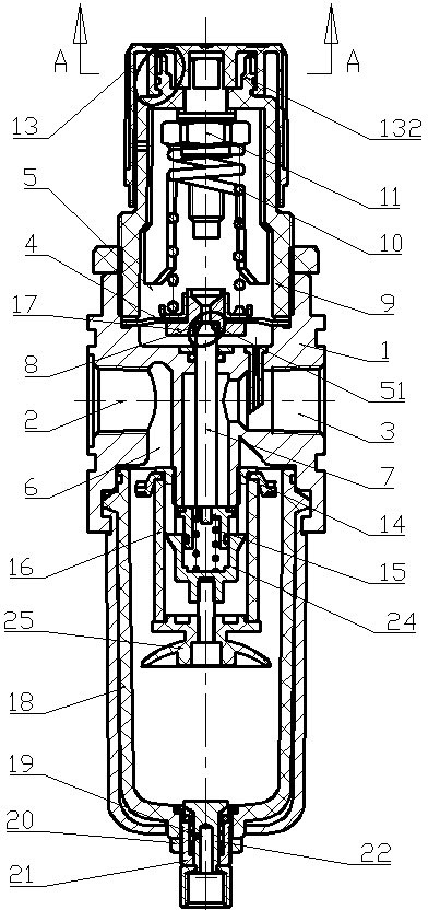
[0030] figure 1 It is a filter pressure reducing valve of the present invention, which includes a valve body 1, and the left and right sides of the valve body 1 are respectively provided with a high-pressure inlet 2 and a low-pressure outlet 3; it also includes a pressure regulating assembly connected to the upper side of the valve body 1 And the air filter assembly connected to the lower part of the valve body 1 , the valve body 1 and the pressure regulating assembly are separated into an upper diaphragm chamber 5 and a lower valve core chamber 6 through a diaphragm assembly. The spool chamber 6 is provided with a spool 7 capable of moving up and down, the bottom end of the spool 7 is fixedly connected with the spool seat 14, and the connection seat 24 between the spool seat 14 and the valve body is fixed. A balance spring 15 is provided between them. It is used to block the communication between the high-pressure inlet 2 and the low-pressure outlet 3 when the pressure reduc...


PUM


Abstract

The invention discloses a filter decompression valve, which comprises a valve body, the left and right sides of the valve body are respectively provided with a high-pressure inlet and a low-pressure outlet; a pressure regulating assembly: the pressure regulating assembly is arranged at one end of the valve body , the valve body and the pressure regulating assembly are separated into a diaphragm chamber and a valve core chamber by a diaphragm assembly, and the valve core in the valve core chamber presses against the diaphragm assembly in the diaphragm chamber to realize the diaphragm Opening and closing connection between the film cavity and the valve core cavity; the diaphragm assembly is provided with a groove at the connection with the valve core, and an air flow is provided between the valve core and the inner peripheral surface of the groove. Through the gap, a seal is provided between the valve core and the diaphragm seat. The air-tight structure of the pressure reducing valve can ensure the airtightness of the pressure reducing valve, and at the same time, the pressure can be reset accurately. Widely used in various pneumatic systems.

Description

technical field [0001] The invention relates to a decompression valve used in a pneumatic circuit, in particular to a filter decompression valve. Background technique [0002] In the pneumatic system, the filter pressure reducing valve can filter the gas and stabilize the pressure to keep the gas pressure in a constant state, reducing the damage to hardware such as valves or actuators due to sudden changes in the gas source pressure. The existing filter pressure reducing valve has the problem of poor airtightness. The reason is that the valve core of the pressure reducing valve and the diaphragm seat are airtightly matched. The existing valve core is generally made of rigid materials. The cylindrical valve core rod and the semi-spherical valve core head made of elastic material are fixedly connected, and a semi-spherical groove matching the valve core head is formed on the diaphragm seat. This air-tight fit method requires high machining accuracy of the valve core head, and...

Claims


Application Information

Patent Timeline
Patent Type & Authority Applications(China)
IPC IPC(8): F16K1/00F16K1/46F16K31/126F16K35/00B01D35/04
Inventor 林建良查方圣金汉锡
Owner 浙江三正气动有限公司
Why Eureka
Try Eureka