Heat sink and led lamp with heat sink

A technology of heat dissipation device and heat dissipation substrate, which is applied to cooling/heating devices of lighting devices, lighting devices, lighting and heating equipment, etc., which can solve the problems of poor heat dissipation effect, chaotic wind direction, and inability to effectively dissipate heat, and achieve good heat dissipation effect, Improved cooling effect and simple structure

Inactive Publication Date: 2011-12-21
广州南艺灯光音响实业有限公司
View PDF3 Cites 0 Cited by
  • Summary
  • Abstract
  • Description
  • Claims
  • Application Information

AI Technical Summary

Problems solved by technology

[0002] With the development of semiconductor technology, the application of high-power LEDs in the field of lighting is becoming more and more extensive. Since high-power LED light sources can only work normally at a certain temperature, the heat dissipation of high-power LEDs must be considered. Only when the temperature does not exceed a certain range can the life of the light source be ensured. The existing heat dissipation device generally includes a heat dissipation substrate, a heat pipe connected to the heat dissipation substrate, and a fan arranged on one side of the heat pipe. The side close to the heat dissipation substrate is the air outlet. In this structure, the wind from the fan directly blows on the heat dissipation substrate and the heat pipe to dissipate heat. Due to the blocking of the heat dissipation substrate and heat pipe, the heat from the heat dissipation substrate and heat pipe cannot be blown away directly. In addition, the wind direction is chaotic, and some will The hot air will rebound to the vicinity of the fan, and then the fan will blow the hot air to the heat dissipation substrate and heat pipe, so that the heat cannot be effectively dissipated, and the heat dissipation effect is poor, resulting in a short life of the high-power LED light source

Method used


Image

  • Heat sink and led lamp with heat sink
  • Heat sink and led lamp with heat sink
  • Heat sink and led lamp with heat sink

Examples


Embodiment Construction

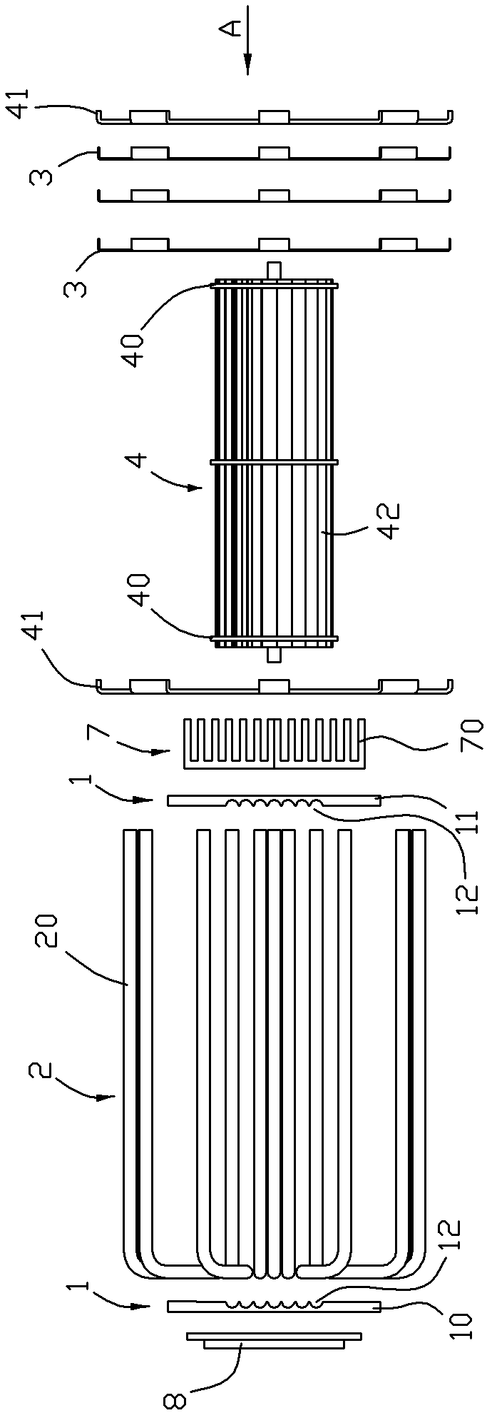
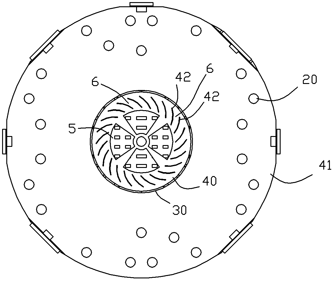
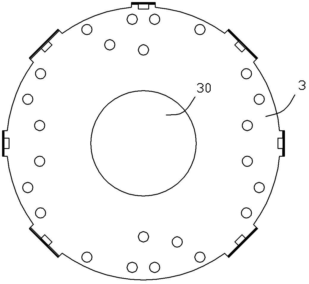
[0026] see Figure 1 to Figure 4 , shows a preferred embodiment of a heat dissipation device of the present invention, including a heat dissipation substrate 1, several heat pipes 2, a row of several heat dissipation fins 3 arranged at intervals ( figure 1 Three cooling fins are schematically drawn in , in actual use, the number of specific cooling fins used can be selected in combination with the length of the heat pipe and the drum fan) and the fan 4, leaving space between the cooling fins Reasonable spacing is used to ensure the smooth flow of heat dissipation. The center of each heat dissipation fin has a central hole 30, so that the center position between the several heat dissipation fins forms a cylindrical accommodation space. The fan is a drum type Fan, the drum-type fan is arranged in the cylindrical accommodation space, each of the heat pipes is partially embedded in the heat dissipation substrate, and the protruding end of each heat pipe has an extension section 20...


PUM


Abstract

The invention relates to a heat-dissipating device and an LED (light emitting diode) lamp with the heat-dissipating device. The heat-dissipating device comprises a heat-dissipating base plate, a plurality of heat-conducting pipes, a row of a plurality of heat-dissipating fins arranged at intervals and a fan, wherein the center of each heat-dissipating fin is provided with a central hole, thus the central position among the plurality of heat-dissipating fins can form a tube-shaped accommodation space; the fan is a drum-type fan, the drum-type fan is arranged in the tube-shaped accommodation space; part of each heat-conducting pipe is embedded in the heat-dissipating base plate, an extending end of each heat-dissipating pipe is provided with an extension part in parallel with the axis of each heat-dissipating fin, each extension part penetrates through each heat-dissipating fin in sequence, the plurality of extension parts are respective distributed along the circumferential direction of the heat-dissipating fins, two ends of the drum-type fan are provided with air inlets, and the whole body of the drum-type fan can form a plurality of air outlets. The structure can realize 360-degree thorough rapid heat dissipation so that heat in the heat-conducting pipe can be rapidly blown away. The heat-dissipating device has a better heat-dissipating effect and a simple structure.

Description

technical field [0001] The invention relates to a heat dissipation device and an LED lamp with the heat dissipation device. Background technique [0002] With the development of semiconductor technology, the application of high-power LEDs in the field of lighting is becoming more and more extensive. Since high-power LED light sources can only work normally at a certain temperature, the heat dissipation of high-power LEDs must be considered. Only when the temperature does not exceed a certain range can the life of the light source be ensured. The existing heat dissipation device generally includes a heat dissipation substrate, a heat pipe connected to the heat dissipation substrate, and a fan arranged on one side of the heat pipe, and the side close to the heat dissipation substrate is the air outlet. In this structure, the wind from the fan directly blows heat on the heat dissipation substrate and heat pipe. Due to the blocking of the heat dissipation substrate and heat pipe...

Claims


Application Information

Patent Timeline
Patent Type & Authority Applications(China)
IPC IPC(8): F21V29/02F21Y101/02F21V29/67F21V29/74F21V29/89
Inventor 陈健强
Owner 广州南艺灯光音响实业有限公司
Why Eureka
Try Eureka