Turbidity Flow Cell

A flow cell and turbidity technology, which is applied in the field of flow cells, can solve the problems of poor sealing performance of flow cells, bubbles generated in flow cells, and inaccurate measurement of instruments, etc., and achieves the effects of good structural sealing, increased accuracy, and enhanced drying effect.

Active Publication Date: 2011-12-21
北京利达科信环境安全技术有限公司
View PDF4 Cites 14 Cited by
  • Summary
  • Abstract
  • Description
  • Claims
  • Application Information

AI Technical Summary

Problems solved by technology

Most of the online water quality monitors currently on the market use a flow cell to be connected to the input pipe of the liquid to be tested and the output pipe of the liquid to be tested, and then installed in the housing of the online water quality monitor. side and fixed in the shell of the online water quality monitor, and the flow cell used mostly adopts a tubular or rectangular glass structure. The flow cell with this structure has poor sealing performance, and because the light source emitting device and the receiving device are set in the flow cell External causes inaccurate instrument measurement, bubbles in the flow cell, etc.

Method used


Image

  • Turbidity Flow Cell
  • Turbidity Flow Cell
  • Turbidity Flow Cell

Examples


Embodiment Construction

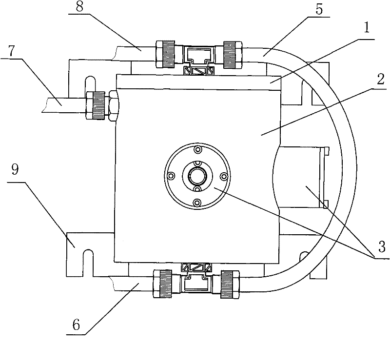
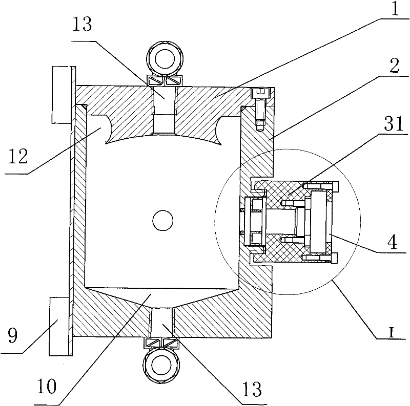
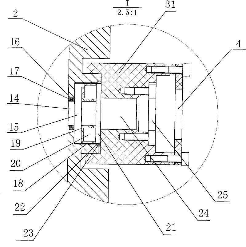
[0037] Preferred embodiments of the present invention will be further described below in conjunction with the accompanying drawings. figure 1 It is the front view of the turbidity flow cell of the present invention, figure 2 for figure 1 Longitudinal sectional view of the turbidity flow cell, image 3 for figure 2 Partial enlarged view of I, Figure 4 for figure 1 top view of Figure 5 It is a top view of the turbidity flow cell cover of the present invention, Figure 6 for Figure 5 side sectional view of Figure 7 It is a cross-sectional view of the base of the flow cell body when the transmitter / receiver housing is not installed, Figure 8 for Figure 7 Partial enlarged view of I, Figure 9 is the sectional view of the transmitter / receiver housing, Figure 10 is the side view of the stepped plane lens, Figure 11 for Figure 10 top view of Figure 12 is the side view of the drying box, Figure 13 for Figure 12 top view.

[0038] The invention provides a ...


PUM


Abstract

The invention provides a turbidity flowing cell. Trough holes on the side wall of the main body of the flowing cell form two light source transmission holes through which light can penetrate, light emitted by a light-emitting device is directly transmitted into the inner cavity of the flowing cell by virtue of one light source transmission hole, and the light in the inner cavity of the flowing cell is received by a receiving device by virtue of the other light source transmission hole. The invention also provides another turbidity flowing cell which also comprises a transmitting / receiving device besides the main body the flowing cell, wherein one part of the transmitting / receiving device is embedded into the side wall of the main body of the flowing cell with certain thickness to form an integrated structure with the main body of the flowing cell. The flowing cell and a light source structure form a unified whole, thus linear distance between sample liquid in the flowing cell and a light source is greatly shortened and measuring accuracy is improved.

Description

technical field [0001] The invention relates to flow cell technology, in particular to a turbidity flow cell used in an online water quality monitor. Background technique [0002] With the development of the economy and the improvement of people's living standards, the problems of environmental pollution and water pollution are becoming more and more serious. In order to analyze the pollution degree of water quality, it is necessary to detect various parameters in water, such as COD (or hydrocarbons, chlorophyll A, rhodamine), ammonia nitrogen, chromaticity, turbidity, dissolved oxygen, conductivity, temperature and pH and other parameters . Most of the online water quality monitors currently on the market use a flow cell to be connected to the input pipe of the liquid to be tested and the output pipe of the liquid to be tested, and then installed in the housing of the online water quality monitor. side and fixed in the shell of the online water quality monitor, and the fl...

Claims


Application Information

Patent Timeline
Patent Type & Authority Applications(China)
IPC IPC(8): G01N21/05
Inventor 王欣
Owner 北京利达科信环境安全技术有限公司
Why Eureka
Try Eureka