A wiring method for realizing fully automatic operation of line DC ice melting

A DC ice melting, fully automated technology, applied in the installation of cables, electrical components, overhead installation, etc., can solve the problems of high operating intensity and difficulty, long line downtime, and impact on ice melting efficiency, etc., to achieve convenient operation, The effect of improving reliability and reducing line downtime

Active Publication Date: 2011-12-21
SOUTHWEST ELECTRIC POWER DESIGN INST OF CHINA POWER ENG CONSULTING GROUP CORP +1
View PDF3 Cites 6 Cited by
  • Summary
  • Abstract
  • Description
  • Claims
  • Application Information

AI Technical Summary

Problems solved by technology

[0003] Judging from the current application of DC deicing devices in the power grid, the connection (or disconnection) of the output pipe bus of the deicing device and the deicing line, and the short circuit (or disconnection) of the deicing circuit are generally realized manually. When freezing, the operator uses tools and temporary short-circuits to connect the busbar of the ice-melting pipe to the line in the substation where the ice-melting device is located, and then short-circuits the three-phase line with a temporary short-circuit in the substation on the opposite side of the line to be ice-melted. In the process of connection, connection and removal, the line must be turned into the maintenance state, because the hanging point of the line is often higher than the ground, especially for the 500kV line, the height of the hanging point of the line is generally more than 20m, and the manual operation is not only time-consuming , and the work intensity and difficulty are very high
According to the current field application experience from 2009 to 211, the manual wiring time is longer than the actual melting time of the line, causing the line outage time to be more than twice the line melting time, and it takes more than 10 hours to complete the melting of a 500kV line. Ice-melting efficiency is severely affected
The connection between the busbar of the output pipe of the existing DC ice-melting device and the ice-melting line adopts a manual temporary on-site connection method, which has disadvantages such as long line outage time, high risk, and poor reliability.

Method used


Image

  • A wiring method for realizing fully automatic operation of line DC ice melting
  • A wiring method for realizing fully automatic operation of line DC ice melting
  • A wiring method for realizing fully automatic operation of line DC ice melting

Examples


Embodiment Construction

[0037] All features disclosed in this specification, or steps in all methods or processes disclosed, may be combined in any manner, except for mutually exclusive features and / or steps.

[0038] Any feature disclosed in this specification (including any appended claims, abstract and drawings), unless expressly stated otherwise, may be replaced by alternative features which are equivalent or serve a similar purpose. That is, unless expressly stated otherwise, each feature is one example only of a series of equivalent or similar features.

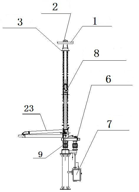
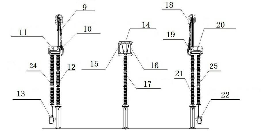
[0039] Such as figure 1 , the special isolating switch for the connection between the DC ice-melting device and the ice-melting line includes a pressure equalizing ring, a moving contact 1, a static contact 1, an insulating porcelain bottle 1, an insulating porcelain bottle 2, a terminal board 1, a terminal board 2, and a vertically open main knife Electric operating mechanism 1 of gate, main knife gate, support column and support platform; i...


PUM


Abstract

The invention discloses a wiring method for realizing full-automatic line direct-current ice-melting operation, relates to a grid power transmission line direct-current ice-melting technique and aims at providing a full-automatic operation method for realizing the connection between a direct-current ice-melting device and an ice-melting line and the short-circuit connection between the direct-current ice-melting device and the threes phases of the ice-melting line. The wiring method is technically characterized in that a special isolating switch for the connection between the direct-current ice-melting device and the ice-melting line is used for realizing the automatic connection between one side of the ice-melting line and the direct-current ice-melting device, and a special common-fixed-contact isolating switch for the short-circuit connection of the direct-current ice-melting line is used for realizing the automatic short-circuit connection of the A phase, the B-phase and the C-phase of the ice-melting line. The wiring method realizes the full-automatic wiring for the power transmission line direct-current ice-melting, can greatly shorten the line cutoff time during ice-melting, and has the advantages of small occupied area and good implementation feasibility.

Description

technical field [0001] The invention relates to a DC ice-melting technology for power grid transmission lines, in particular to a fully automatic operation method for three-phase short-circuiting of a DC ice-melting device, an ice-melting line, and an ice-melting line. Background technique [0002] The threat of ice disaster has always been a major technical problem that the power system industry is struggling to deal with. In recent years, with changes in global climate conditions, low-temperature, rainy, snowy and freezing weather has frequently occurred in southern, central, and northern China, which has repeatedly caused large-scale and long-term outages of power transmission lines in various provinces in our country, causing huge losses to the national economy and people's lives. . In order to prevent this situation from recurring, after the ice disaster in 2008, my country's electric power science and technology workers independently carried out the research and devel...

Claims


Application Information

Patent Timeline
Patent Type & Authority Applications(China)
IPC IPC(8): H02G7/16
CPCH02G7/16
Inventor 吴怡敏饶宏黄晓明余波傅闯蔡德江冯小明黎小林牟小松徐小丽王强郑勇
Owner SOUTHWEST ELECTRIC POWER DESIGN INST OF CHINA POWER ENG CONSULTING GROUP CORP
Why Eureka
Try Eureka