Milling tools and cutting elements for milling tools

A technology of cutting elements and tools, applied in milling cutting inserts, tools for milling machines, workpieces, etc., can solve problems such as damage to positioning accuracy, deterioration of cutting edge positioning repeatability, etc., and achieve the effect of simplifying positioning accuracy

Active Publication Date: 2011-12-21
LEITZ GMBH & CO KG
View PDF10 Cites 14 Cited by
  • Summary
  • Abstract
  • Description
  • Claims
  • Application Information

AI Technical Summary

Problems solved by technology

However, this configuration impairs the positioning accuracy, which leads to a poorer repeatability of the positioning of the cutting edges in the case of multiple installations

Method used


Image

  • Milling tools and cutting elements for milling tools
  • Milling tools and cutting elements for milling tools
  • Milling tools and cutting elements for milling tools

Examples


Embodiment Construction

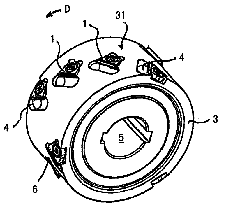
[0056] The milling tool comprises a carrier body 3 with a cutting element 1 inserted into a recess 2 of the carrier body and screwed to the carrier body 3 by countersunk screws 6 . In front of each cutting element 1 there is provided a chip space 4 for receiving chips generated during machining of a workpiece. From figure 1 It can be seen that the outer cutting element 1 is arranged in the axially open recess 2 and is not guided on its axial circumferential wall. The cutting element 1 is arranged such that a helical overall cutting edge is formed by the individual cutting edges 11 . The milling tool can be connected to a drive shaft (not shown in detail here) of a machining tool via an axial bore 5 provided in the carrier body 3 .

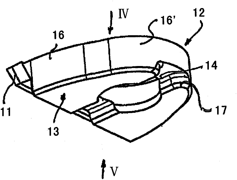
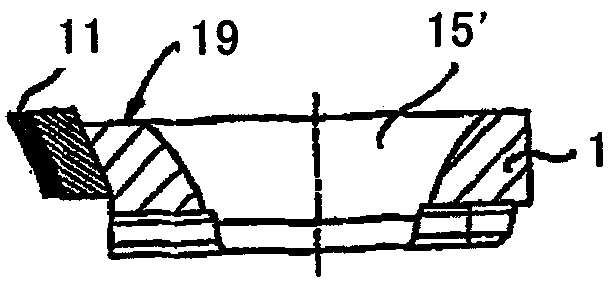
[0057] Each cutting element 1 has a symmetrical shape, which tapers toward the side opposite the cutting edge 11 (cutting edge) and is substantially triangular in design. The region 12 lying opposite the cutting edge 11 is rounded with a constan...


PUM


Abstract

The invention relates to a milling tool for machining non-metallic materials, in particular wood, wood-based materials and plastics, which has a carrier (3) into which a corresponding number of tools can be inserted in the radial direction on the circumferential side A plurality of cutting elements (1) in an extended recess (2), which can be screwed to the carrier (3) via holes (15), said cutting elements being plate-shaped and in cross-section Basically triangular in shape and provided with a cutting edge (11) on one side edge, it is characterized in that the cutting element (1) has the following features: a) the area (12) opposite the cutting edge (11) is inverted circle, b) a groove (14) is provided in the underside (13) extending substantially at right angles to the cutting edge (11), c) the hole (15) divides the groove (14) preferably into two regions , is also characterized by the following feature of the hollow slot (2): d) extends upwards in the radial direction from the bottom (21) of the hollow slot serving as a support surface for the cutting element (1) tab (22), which is associated with the groove (14), e) a radial threaded hole (23), which preferably divides the tab (22) into two regions , and f) the cutting element (1) is only characterized by its underside (13), the side wall (17 or 18) of the groove (14) and the A part of the area (12) is in contact with said cavity (2).

Description

technical field [0001] The invention relates to a milling tool for machining non-metallic materials, especially wood, wood-based materials and plastics, which has a carrier body into which a corresponding number of cavities extending in radial direction can be inserted on the circumferential side. A plurality of cutting elements in grooves, which can be screwed to the carrier body via holes, the cutting elements are plate-shaped and substantially triangular in cross section and are provided with cutting edges on one side edge . [0002] The invention also relates to a cutting element for a milling tool having the features stated in the preamble of claim 15 . Background technique [0003] Such milling tools and cutting elements that can be used therewith are known, for example, from EP 0861144 B1 or US Pat. No. 6,659,694 B1. [0004] In the known tool, the individual cutting elements are fixed tangentially with respect to the outer surface of the carrier by means of a centr...

Claims


Application Information

Patent Timeline
Patent Type & Authority Applications(China)
IPC IPC(8): B27G13/04B23C5/04B23C5/22
CPCB27G13/04B23C2210/168B23C5/04B23C2200/165B23C2200/0416B23C5/2221B23C2226/315Y10T407/1936Y10T407/27B23C5/2213
Inventor A·基塞尔巴赫J·格雷夫H·埃伦施佩格
Owner LEITZ GMBH & CO KG
Why Eureka
Try Eureka