

Pneumatic pipeline transmission container and intelligent pipeline transmission system
A transmission container and pneumatic pipeline technology, applied in the field of intelligent pipeline material transmission system, can solve the problems that the system cannot run stably, is easily affected by weather factors, and the cable car type material transmission system has not been widely used.
- Summary
- Abstract
- Description
- Claims
- Application Information
AI Technical Summary
Problems solved by technology
Method used
Image

Examples
Embodiment 1
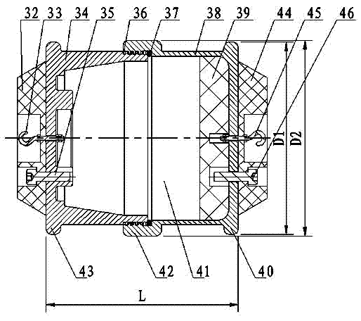
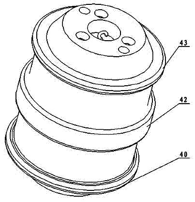
[0016] Embodiment one: as figure 2 As shown, a pneumatic pipeline transport container includes a sample box seat 34 and a sample box cover 38 assembled together for use together. Both the sample box seat 34 and the sample box cover 38 include an open end and a closed end and are both hollow cylinders. shape structure; the outer edge of the closed end of the sample box seat is provided with a first annular protrusion 43; the outer edge of the open end of the sample box cover is provided with a second annular protrusion 42 that surrounds a circle and extends axially. The circumferential outer edge of the closed end of the lid is provided with a third annular projection 40; the gap between the second annular projection 42 and the inner wall of the pipeline is 3-4 mm; the first annular projection 43 and the third annular projection The gap between 40 and the inner wall of the pipeline is 6-7 millimeters. The outer edge of the open end of the sample box seat is provided with an e...
Embodiment 2
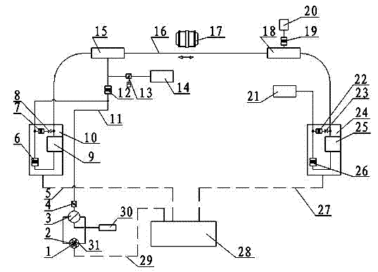
[0022] The similarities between this embodiment and Embodiment 1 will not be repeated, and the difference is that, as figure 1 As shown, a kind of intelligent pipeline material transmission system, it comprises transmission pipeline 16 and the first transceiving unit 10 and the second transceiver unit 24 that are positioned at the two ends of transmission pipeline 16, it is characterized in that the operation in the transmission pipeline is as described in embodiment 1 The pneumatic tube transfer container described above.
[0023] The intelligent pipeline material transmission system also includes a flow direction converter 3 arranged on the transmission pipeline 16, a flow direction controller (12, 19), first to fourth intake and exhaust ports (14, 20, 21, 30), and a fan 1 And realize the intelligent control cabinet 28 of control operation, control cable or optical cable (5,27,29). The first transceiver unit 10 and the second transceiver unit 24 at both ends are connected tog...
PUM
| Property | Measurement | Unit |
|---|---|---|
| Width | aaaaa | aaaaa |
| Width | aaaaa | aaaaa |
Abstract
Description
Claims
Application Information