Form rolling method for involute gear

An involute gear and rolling technology, applied in the field of forming and rolling, can solve the problems of complicated gear manufacturing operations, increased man-hours and manufacturing costs, etc.

Active Publication Date: 2011-12-28
AISIN SEIKI KK
View PDF5 Cites 12 Cited by
  • Summary
  • Abstract
  • Description
  • Claims
  • Application Information

AI Technical Summary

Problems solved by technology

Therefore, the manufacturing operation of the gear will be complicated, and man-hours and manufacturing costs will be increased

Method used


Image

  • Form rolling method for involute gear
  • Form rolling method for involute gear
  • Form rolling method for involute gear

Examples


Embodiment Construction

[0028] Hereinafter, an embodiment of a form rolling method for an involute gear will be explained with reference to illustrations of the accompanying drawings.

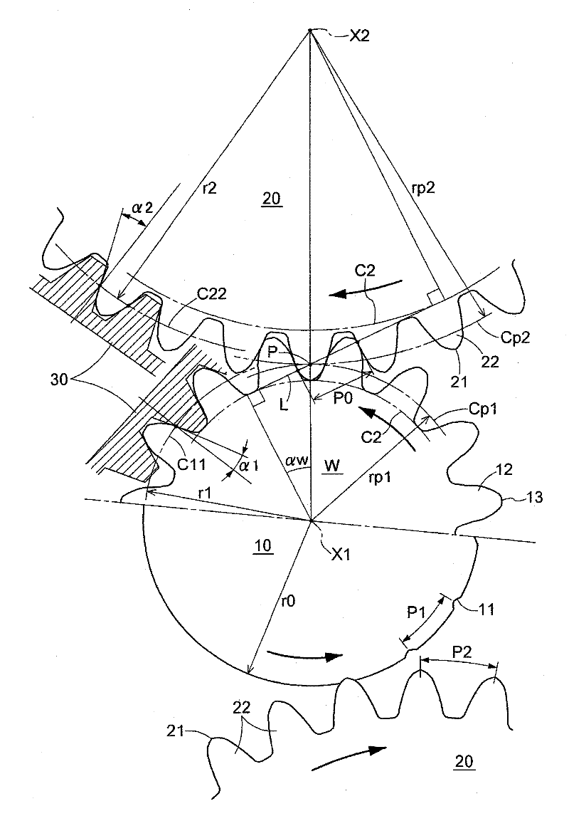
[0029] The form rolling method for an involute gear according to an embodiment relates to a method for forming a gear by form rolling an involute gear while using a workpiece including a cylindrical configuration ( That is, hereinafter referred to as the gear) when optimizing the contact of the circular die (i.e., hereinafter referred to as the die) with respect to the workpiece, and then further by properly pressing the die into the workpiece, with high precision and mechanical characteristics above is excellent.

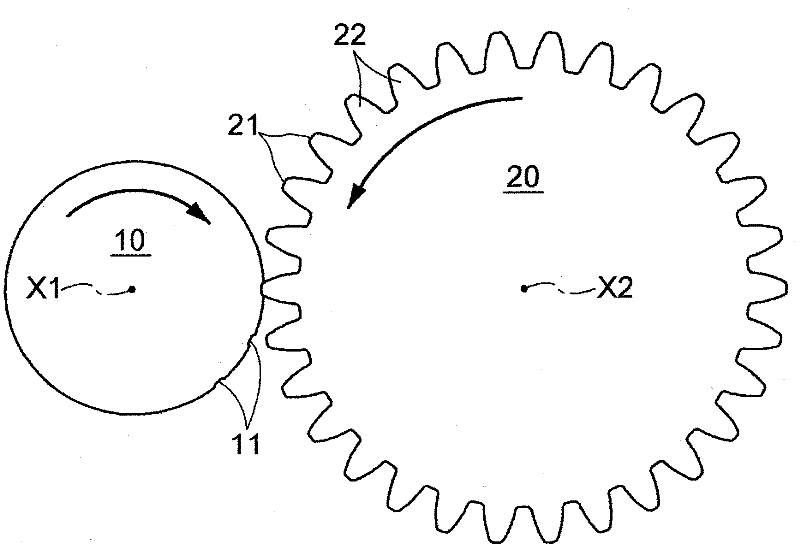
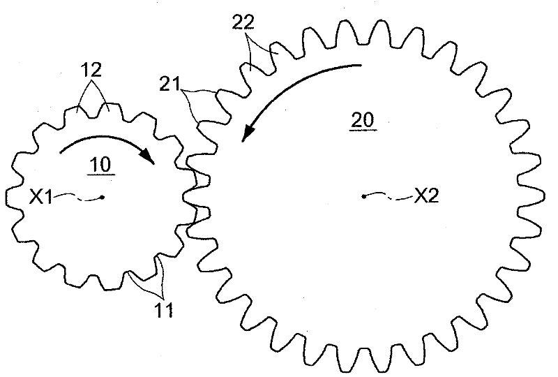
[0030] Such as figure 1 As shown, form rolling of the workpiece 10 is performed using a die 20 . figure 1 The lower half of the figure shows the state that the die 20 starts to press the workpiece 10 . figure 1 The upper part in shows the completed state of the form rolling process. The pitch P1 of ...


PUM


Abstract

A form rolling method for an involute gear, which includes a work piece (10) including a cylindrical outer peripheral surface having a predetermined radius, and a round die (20) with an Involute tooth profile including an addendum pitch corresponding to a pitch defined by dividing a length of an outer circumference of the work piece (10) by number of teeth of the involute gear. The round die (20) is pressed to the work piece(10) while rotating when form rolling the involuete gear.

Description

technical field [0001] The present disclosure generally relates to a method of form rolling for involute gears. Background technique [0002] According to a known method for forming gears, a die on which a predetermined tooth profile is formed is extruded to a cylindrical blank to form a gear having a predetermined configuration. In these cases, for example, a circular die for form rolling is used, which has a tooth profile capable of engaging the gear wheel to be produced. Typically, two circular dies for form rolling are rotated and moved close to the workpiece to press the dies to the workpiece. The circular die used for form rolling is progressively squeezed and thus moved to the final position to form the gear. [0003] In the case of forming a gear by using a circular die for form rolling, first, the tooth tops of the teeth of the circular die for form rolling are in contact with the surface of the workpiece. Intermittent extrusion notches are formed on the surface ...

Claims


Application Information

Patent Timeline
Patent Type & Authority Applications(China)
IPC IPC(8): B21H5/00
CPCB21H5/02Y10T29/49462Y10T29/49467Y10T29/49471
Inventor 永田英理栗田信明
Owner AISIN SEIKI KK
Why Eureka
Try Eureka