
Drilling method of a pcb board drilling machine

A technology of PCB board and processing method, applied in the field of PCB processing of printed circuit board, can solve the problems of unstable Z-axis processing process, inconsistent position of front and back holes of PCB, Z-axis vibration and high noise, etc.

Active Publication Date: 2011-12-28
HANS CNC SCI & TECH
View PDF7 Cites 19 Cited by
  • Summary
  • Abstract
  • Description
  • Claims
  • Application Information

AI Technical Summary

Problems solved by technology

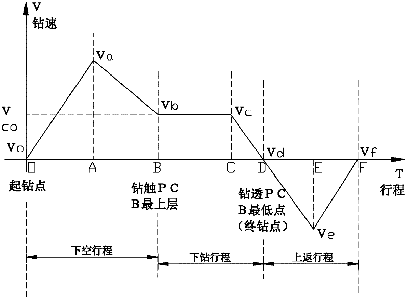
[0008] The inventor repeatedly analyzes figure 1 Later, I gradually realized that points Va and A are the speed mutation points when the Z-axis goes down, and Vb and B points are the speed mutation points during the Z-axis drilling stage; due to the existence of these two speed mutation points, and the A and B sections are tool The stroke section from empty drilling to contacting the PCB surface will result in too high speed and large tool bending when the tool touches the processing surface, which will inevitably cause too much vibration and noise on the Z axis during drilling, resulting in PCB positive and negative faces. Bit inconsistency, thus bringing instability to the Z-axis machining process

Method used


Image

  • Drilling method of a pcb board drilling machine
  • Drilling method of a pcb board drilling machine
  • Drilling method of a pcb board drilling machine

Examples


Embodiment Construction

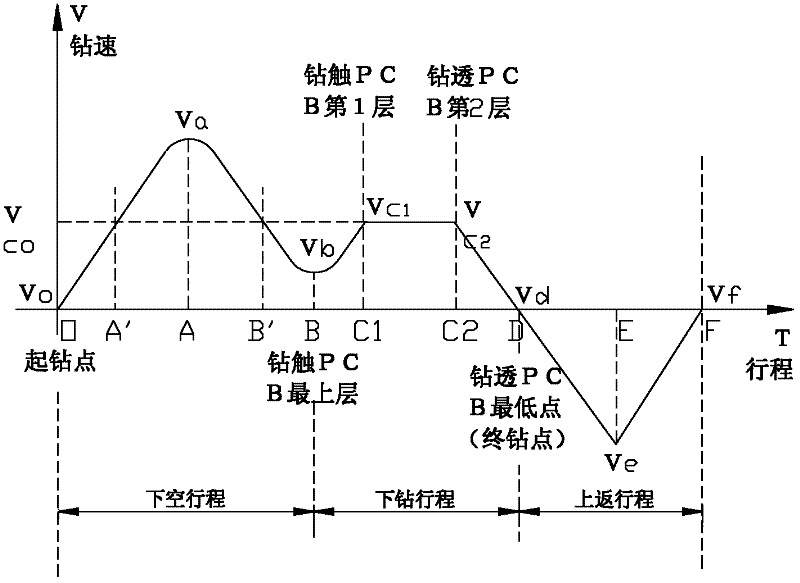
[0024] Such as figure 2 , is a schematic block diagram of an embodiment of the drilling method of the present invention for a PCB board drilling machine. The PCB board is clamped on the platform of the PCB board drilling machine, and the PCB board includes the uppermost protective layer, the middle circuit board layer, and the lower backing board layer successively. The processing method is based on having PLC function and It is implemented on the PCB CNC drilling machine with UMAC motion control card.

[0025] The processing method includes controlling the drill shaft of the drilling rig to perform a downward stroke O-D segment for forward rotation, and an upper return stroke D-F segment for reverse rotation; the downward stroke O-D segment includes an idling lower stroke O-B segment, drilling Drilling stroke section B-D; the downstroke O-B section includes: the speed-up section O-A section increasing from zero speed Vo, the deceleration section A-B section starting from th...


PUM


Abstract

The invention relates to a drilling processing method of a PCB (printed circuit board) board drilling machine, which comprises a downward stroke controlling a drill spindle of the drilling machine to rotate forwards, and an upward return stroke controlling the drill spindle of the drilling machine to rotate reversely, wherein the downward stroke comprises a downward noncutting stroke and a downward drilling stroke; the downward noncutting stroke comprises an acceleration section and a deceleration section, the deceleration section keeps until a touch pad rotation speed Vb is achieved when a drill cutter touches a protective layer; the downward drilling stroke comprises a constant speed section in which drilling is carried out at a constant rotary speed Vco, and a deceleration section for reducing the rotary speed after the drill cutter touches a base plate layer; and the upward return stroke starts when the base plate layer is drilled through, the constant rotary speed Vco starts whenthe drill cutter touches a circuit board layer and ends when the circuit board layer is drilled through by the drill cutter, the deceleration section is adjusted in the processing method to make the touch pad rotary speed Vb lower than the constant rotary speed Vco, and an acceleration section in which the rotary speed increases gradually also exists between the reduced touch pad rotary speed Vb and the constant rotary speed Vco. In the processing method provided by the invention, simple and effective steps can be adopted, and vibration noise of the drilling spindle and PCB front and back surface hole site deviation are further reduced through reducing drilling entering rotary speed.

Description

technical field [0001] The invention relates to a method for processing a printed (manufactured) circuit board (PCB), more specifically, the invention relates to a method for drilling holes on a printed circuit board (PCB). Background technique [0002] In actual production, the printed circuit board PCB board to be processed generally consists of four layers, the uppermost layer is an aluminum plate (to protect the PCB from the influence of the presser foot), the middle is a two-layer circuit board, and the bottom layer is a backing plate (to protect the drilling rig Platform panels are protected from knife scratches). [0003] The precision machining of printed circuit board (PCB) holes requires the drilling machine to have the characteristics of high speed, high precision and high stability. For this reason, the key process equipment for processing printed circuit boards is a multi-axis cascaded CNC drilling machine to ensure the normal operation of the mechanical equipm...

Claims


Application Information

Patent Timeline
IPC IPC(8): B23B35/00
Inventor 宋福民谭艳萍高云峰
Owner HANS CNC SCI & TECH
Learn More