Track hanging conveyor

A technology of conveyors and track cranes, which is applied in the direction of conveyors, conveyor objects, transportation and packaging, etc. It can solve the problems of difficult steering of the conveyor system, high energy consumption of conveyors, and large running resistance, so as to achieve obvious energy saving effects and avoid interruptions. The effect of bringing accidents and eliminating influence

Inactive Publication Date: 2011-12-28
李超
View PDF6 Cites 22 Cited by
  • Summary
  • Abstract
  • Description
  • Claims
  • Application Information

AI Technical Summary

Problems solved by technology

[0003] In order to solve the problems of the existing belt conveying system, such as the large running resistance caused by the idlers, the high energy consumption of the conveyor, the difficulty in turning the conveying system, the need for unloading, the deviation of the belt, and the wear of the idlers, the invention provides a track-hanging type Conveyor, install a ring track system on both sides of the conveyor belt, use a hanging conveyor belt, and there are hanging buckles on both sides of the hanging conveyor belt (the hanging conveyor belt has applied for another patent protection at the same time), It is connected with the hanging pulley block (the hanging pulley has applied for another patent protection at the same time), and provides hanging support for the conveyor belt. All idlers, through the existing conveyor belt drive technology, use the drive roller to drive the suspended conveyor belt to run, and the suspended conveyor belt pulls the suspended pulley to roll along the circular track to realize the feeding and transfer of the traditional belt conveyor system. With the unloading function, due to the forced guidance of the track, the deviation of the conveyor belt is avoided, and at the same time, it can conveniently solve the problem of turning the conveyor system, saving the manufacturing cost and operating cost of the conveyor system

Method used


Image

  • Track hanging conveyor
  • Track hanging conveyor
  • Track hanging conveyor

Examples


Embodiment Construction

[0035] The present invention will be further described below in conjunction with the accompanying drawings and implementation examples.

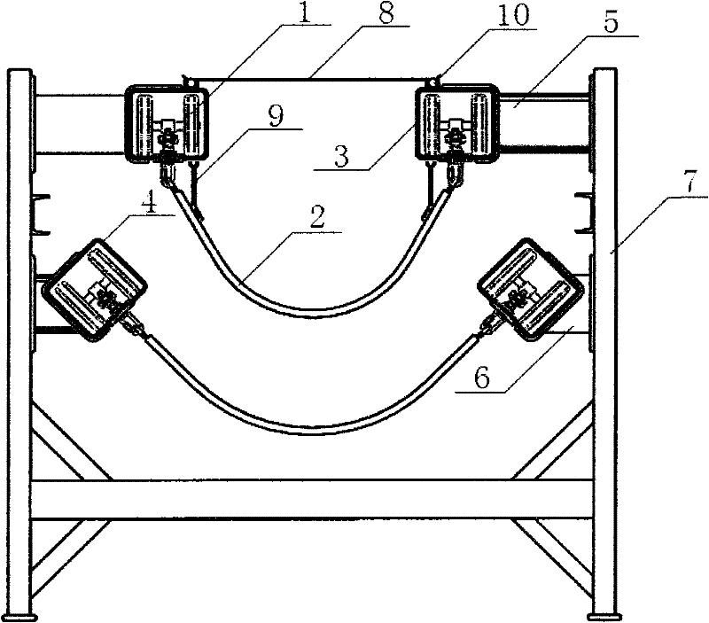
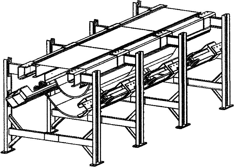
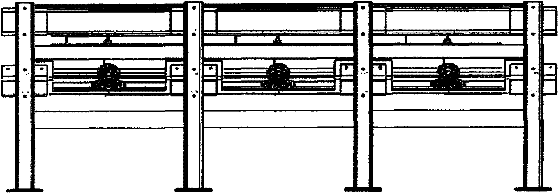
[0036] figure 1 , figure 2 and image 3 The schematic diagrams of different perspectives of the running section of the track-mounted conveyor are shown in the figure respectively. figure 1 Among them, the running section is fixed by a hanging pulley block (1), a hanging conveyor belt (2), a box-type guide rail (3), an open box-type guide rail (4), a vertical guide rail fixing frame (5), and an oblique guide rail frame (6), conveyor frame assembly (7), dust cover (8), rubber baffle assembly (9), and fixing strip assembly (10). The opening of the slot is downward, and the two rails are installed symmetrically and parallel. Figure 5 The closed box-type guide rail shown in the figure is in the shape of a rectangular tube, which is formed by folding steel plates. The 24 marked in the figure is the walking track (24), and the interval betwee...


PUM


Abstract

The invention relates to a rail suspension type conveyor, which is the combination of a belt type material conveying system and a rail delivery technology, reflects the continuous conveying feature of belt type conveying and the low-energy consumption feature of the rail transport, and changes the form that carrier rollers are adopted to support a belt in the traditional belt type conveying system. In the rail suspension type conveyor, by utilizing the traditional conveying system driving and control technology, two sides of a conveying belt are respectively provided with a set of annular guide rail system, a suspension pulley block is used to suspend a suspension conveyor belt so as to provide the suspension support for the conveyor belt; a driving roller is used for driving the suspension conveyor belt to operate, and the suspension conveyor belt drags the suspension pulley block to roll and travel along an annular rail so as to realize the feeding, transshipping and unloading functions of the traditional belt type conveying system; meanwhile, the steering function of a single conveying system can be realized to improve the safety of the conveying system; all carrier rollers in the running section are cancelled, and the energy conservation effect is obvious; and the rail suspension type conveyor is particularly suitable for the long-distance transport and the conveying occasions, such as a mine laneway and the like, with greater conveying amount.

Description

Technical field [0001] The invention relates to the combination of belt material conveying system and rail conveying technology, embodies the continuous conveying characteristics of belt conveying and the low energy consumption characteristics of rail conveying, changes the way that the traditional belt conveying system uses rollers to support the belt, and utilizes the current Some conveyor system drive and control technologies install a set of ring guide rail systems on both sides of the conveyor belt, use the hanging pulley block to hang the hanging conveyor belt, provide hanging support for the conveyor belt, and the driving roller drives the hanging The hanging conveyor belt pulls the hanging pulley and rolls along the circular track to realize the loading, transfer and unloading functions of the traditional belt conveyor system, and at the same time realize the steering function of a single conveyor system, improving the efficiency of the conveyor system. For safety, all...

Claims


Application Information

Patent Timeline
Patent Type & Authority Applications(China)
IPC IPC(8): B65G15/08B65G21/22B65G41/00
Inventor 李超
Owner 李超
Why Eureka
Try Eureka