A kind of spreader and front hanger

A technology of reachstackers and spreaders, applied in the field of reachstackers and spreaders of reachstackers, which can solve the problems of increasing the difficulty of disassembly and reducing the working efficiency of reachstackers, and achieve the effect of saving time, saving disassembly time and simple assembly

Active Publication Date: 2011-12-28
SANY MARINE HEAVY IND +1
View PDF6 Cites 8 Cited by
  • Summary
  • Abstract
  • Description
  • Claims
  • Application Information

AI Technical Summary

Problems solved by technology

When disassembling, the electrical circuit and hydraulic pipeline should also be disassembled, which will increase the difficulty of disassembly and reduce the working efficiency of the reach stacker

Method used


Image

  • A kind of spreader and front hanger
  • A kind of spreader and front hanger
  • A kind of spreader and front hanger

Examples


Embodiment Construction

[0032] The core purpose of the present invention is to provide a sling, which can be loaded and unloaded quickly and can improve the working efficiency of the front hanger. In addition, another core of the present invention is to provide a front stacker comprising the above-mentioned spreader.

[0033] Without loss of generality, this article takes the application of the spreader in the reachstacker as an example for introduction, and those skilled in the art should understand that the application of the spreader provided by the present invention in other reachstackers is not excluded.

[0034] In order to enable those skilled in the art to better understand the technical solutions of the present invention, the present invention will be further described in detail below in conjunction with the accompanying drawings and specific embodiments.

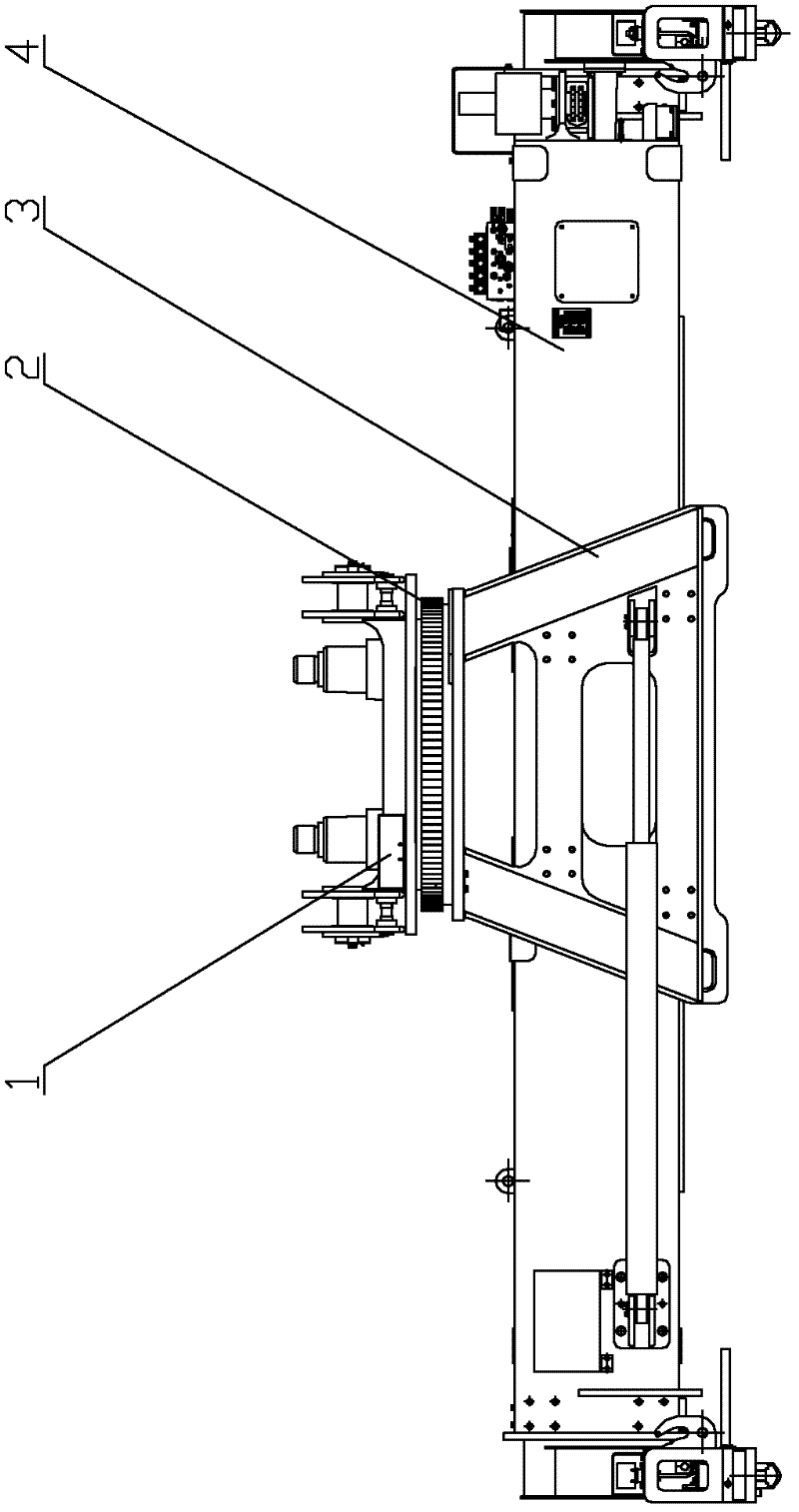
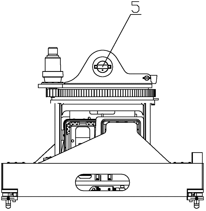
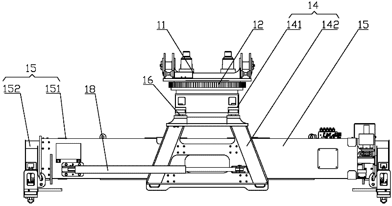
[0035] Please refer to image 3 , image 3 It is a structural schematic diagram of a sling provided by the present invention.

[0036...


PUM


Abstract

The invention discloses a lifting device of a front crane. The lifting device comprises an upper turntable (11) connected to a boom of the front crane, and a lower turntable (14) provided with a lifting crossbeam (15). The upper turntable (11) is connected to the lower turntable (14) through a slewing bearing (12), such that the upper turntable and the lower turntable can rotate relative to each other. The lower turntable (14) comprises an upper connecting frame (141) rigidly connected to the slewing bearing (12) and a lower cage (142) detachably connected to the upper connecting frame (141).The lifting crossbeam (15) is arranged on the lower cage (142). When the lifting device is disassembled, an oil cylinder and a damping pin between the turntables and the boom are not required to be disassembled. Therefore, disassembling is simplified, disassembling time is saved, and time for disassembling electric and hydraulic controlling pipelines on the turntables is saved. With the lifting device provided by the invention, assembling and disassembling are fast, and the work efficiency of the front crane is improved. Also, the invention provides a front crane with the lifting device.

Description

technical field [0001] The invention relates to the technical field of hoisting tools, in particular to a hoisting tool for front hanging. In addition, the present invention also relates to a front hanger comprising the above-mentioned spreader. Background technique [0002] Reach stacker is a typical reach stacker, which is mainly used for port container handling. The spreader is the working device of the reach stacker. Before handling, the spreader is aligned with the container, and then the container is locked to ensure that the container will not fall during the handling process. , Unlock the spreader when it arrives at the designated place, and put down the container. [0003] Please refer to figure 1 with figure 2 , figure 1 It is a structural schematic diagram of a typical reachstacker spreader in the prior art; figure 2 for figure 1 Left side view of spreader shown. [0004] The spreader of the reach stacker for handling containers includes a turntable and a...

Claims


Application Information

Patent Timeline
Patent Type & Authority Applications(China)
IPC IPC(8): B66C1/10B66C23/62
Inventor 李翠英张细刚樊伟
Owner SANY MARINE HEAVY IND
Why Eureka
Try Eureka