Eureka AIR delivers breakthrough ideas for toughest innovation challenges, trusted by R&D personnel around the world.

Carding machine deflector

A technology of diversion device and carding machine, which is applied in the direction of deburring device, textile and paper making, fiber treatment, etc. It can solve the problems of hair particles, reduce the operation rate and production rate of carding machine, and is not conducive to short-hair carding. Achieve the effects of reducing hair particles, improving operation rate and production rate

Active Publication Date: 2011-12-28
JIANGSU ZHENXIN IND
View PDF16 Cites 0 Cited by
  • Summary
  • Abstract
  • Description
  • Claims
  • Application Information

AI Technical Summary

Problems solved by technology

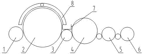
[0002] A carding roller 3 is arranged between the large cylinder 2 and the second breast cylinder 4 of the traditional carding machine, and a trash groove 7 is arranged above the carding roller 3 (such as figure 1 As shown), during the working process of the carding machine, the airflow generated by the feeding of the large cylinder 2 is blocked by the trash groove 7 and flows back, which is not conducive to short-hair carding, and it is easy to produce hair particles in the large cylinder, which reduces the operation rate of the carding machine and production rate

Method used


Image

  • Carding machine deflector
  • Carding machine deflector
  • Carding machine deflector

Examples


Embodiment Construction

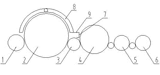
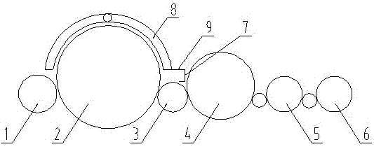
[0019] See figure 2 , The present invention relates to a flow guiding device for a carding machine, which comprises a large cylinder 2 and a two-breasted cylinder 4, and a flow deflector 8 is arranged above the large cylinder 2 and the large cylinder 2 and the second-breasted cylinder The opening roller 3 is arranged between the opening roller 3, and the trash removal groove 7 is provided above the opening roller 3. The front half of the trash removal groove 7 is cut, and the top of the trash removal groove 7 is provided with a windshield 9 which is The wind hood 9 is connected with the deflector 8.

[0020] When the carding machine is working, the airflow generated in the large cylinder 2 is blocked by the windshield 9 and then changes direction. It is cut from the trash slot 7 and is guided to the bottom of the carding machine through the opening roller 3, which is beneficial to the carding of short hairs. , Make the wool net better, reduce the wool particles, improve the run...


PUM


Abstract

The invention relates to a flow guiding device of a combing machine and belongs to the technical field of textile machinery. The flow guiding device comprises a large cylinder (2) and a second chest cylinder (4), wherein a flow guiding cover (8) is arranged above the large cylinder (2); a combing roller (3) is arranged between the large cylinder (2) and the second chest cylinder (4); an impurity receiving groove (7) is arranged above the combing roller (3); a first half part of the impurity receiving groove (7) is cut open; a wind shield cover (9) is arranged at the top of the impurity receiving groove (7); and the wind shield cover (9) is connected with the flow guiding cover (8). In the flow guiding device of the combing machine provided by the invention, the first half part of the impurity receiving groove (7) is cut open; and the top of the impurity receiving groove (7) is provided with the wind shield cover (9), which contributes to guiding out the air stream in the large cylinder, thus a web gets well, neps are reduced, and the operation rate and made-up rate are improved.

Description

Technical field [0001] The invention relates to a flow guiding device of a carding machine, belonging to the technical field of textile machinery. Background technique [0002] In the traditional carding machine, a carding roller 3 is arranged between the big cylinder 2 and the two-breasted cylinder 4, and a trash removal groove 7 (such as figure 1 (Shown), during the working process of the carding machine, the airflow generated by the feeding of the large cylinder 2 is blocked by the trash removal slot 7 and flows back, which is not conducive to short hair combing, and it is easy to produce lint in the large cylinder, which reduces the operation rate of the card And production rate. Summary of the invention [0003] The purpose of the present invention is to overcome the above-mentioned shortcomings and provide a flow guiding device for a carding machine that can improve the operation rate and the production rate. [0004] The purpose of the present invention is achieved as follow...

Claims


Application Information

Patent Timeline
IPC IPC(8): D01G15/12
Inventor 赵丽冬张金妹李浩
Owner JIANGSU ZHENXIN IND
Why Eureka
Eureka Blog
Learn More