Spinning unit for producing low-twist yarn

A twisted yarn and spinning machine technology, which is applied in the field of low-torque ring-spun yarn spinning devices, can solve the problems of inconvenient manufacture and use, high cost, complex structure, etc., and achieve good false twist effect and low residual torque , good yarn quality

Inactive Publication Date: 2011-12-28
NINGBO DECHANG PRECISION TEXTILE MACHINERY +1
View PDF5 Cites 2 Cited by
  • Summary
  • Abstract
  • Description
  • Claims
  • Application Information

AI Technical Summary

Problems solved by technology

[0007] In order to obtain low-torque ring-spun yarn, it is necessary to improve the existing ring-spun spinning method and spinning device, and there have been many studies on this, trying to achieve the goal with the traditional method of reducing the residual torque of the yarn, such as the Chinese patent Document CN1453401A discloses a single-ply torque-free ring-spun yarn processing method and equipment, which proposes to obtain a torque-free yarn on a traditional ring spinning machine through the above-mentioned physical method of reducing the residual torque of the yarn, and the structure is improved. The main point is to install a false twist device and a yarn splitting device between the output roller pair and the yarn guide hook of the existing ring spinning device, but the structure of the spinning device such as the false twist device provided by it is very complicated, which is inconvenient to manufacture and Use; especially the up and down movement of the guide hook on the ring spinning machine will cause the change of the guide angle c, and the set false twist device 2 also needs to follow the up and down movement of the steel ring 7, see image 3 , Figure 4 , this not only makes the whole spinning device very complicated, but also the yarn cannot get a stable false twist effect, the spinning effect is poor, and the cost is high, which does not meet the actual needs of transforming the existing industrialized ring spinning machine

Method used


Image

  • Spinning unit for producing low-twist yarn
  • Spinning unit for producing low-twist yarn
  • Spinning unit for producing low-twist yarn

Examples


Embodiment Construction

[0025] The present invention will be further described in detail below in conjunction with the accompanying drawings and embodiments.

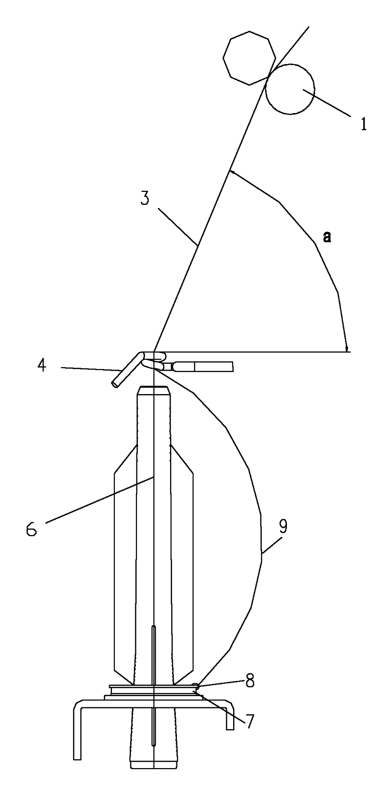
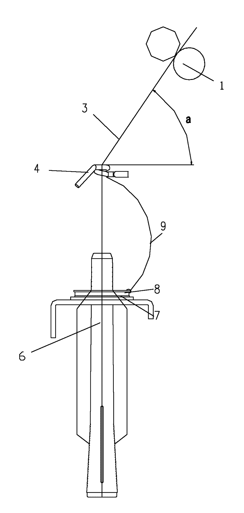
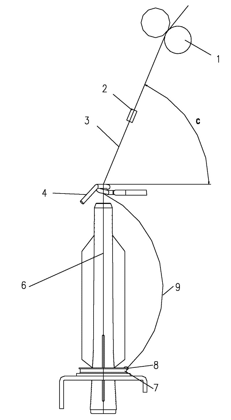
[0026] like Figure 5 , Image 6 Shown, a kind of spinning device of producing low torque yarn, it comprises existing ring spinning machine (see figure 1 and figure 2 ) and the false twist device 2, the false twist device 2 is placed between the output roller pair 1 and the guide hook 4 of the ring spinning machine.

[0027] When the yarn 3 enters the false twist device 2, the yarn 3 and the false twist device 2 form a fixed yarn guide angle b.

[0028] Above-mentioned false twist device 2 must be fixed, and it both can be fixed on the frame 12 of ring spinning machine, or be fixed to other places of machine, also can be fixed on the suitable position of spinning machine periphery.

[0029] The yarn twisting and winding device of the above-mentioned ring spinning machine is the same as the existing spinning machine, including bobbin 6, ri...


PUM


Abstract

Spinning device for producing low-twist yarn, including a ring spinning machine and false twisting device, the false twisting device is placed between the output roller pair and the yarn guide hook of the ring spinning machine, and placed on the yarn guide hook Directly above. The present invention has the advantages that the existing spinning device can be fully utilized and the effect of false twisting can be achieved only by setting the false twisting device directly above the yarn guide hook and fixing it. Therefore, the structure of the whole spinning device is simple, and The existing ring spinning machine can be modified conveniently and at low cost, and the yarn produced is of good quality. It can be applied to Solo spinning, Siro spinning, Sirofi, compact spinning devices of ring spinning or a combination of these devices.

Description

technical field [0001] The invention belongs to the field of fiber yarn spinning, in particular to a low-torque ring-spun yarn spinning device, which enables the yarn to maintain a stable low torque. Background technique [0002] Existing twisting is an important part of short fiber spinning. During twisting, the yarn will generate a large amount of residual torque, which will have a great influence on the quality of subsequent products. For example, in knitted fabrics, due to the change in the internal torsional stress of the yarn, the loops of the fabric will rotate and release the internal torsional stress. As a result, one end of it will lift and protrude from the surface of the fabric, while the other end will stay inside the fabric. This deformation of the loops will increase the curvature of the fabric and produce a deformation like rib effect which is much to be avoided. [0003] At present, there are two main methods to reduce the residual torque of yarn: permanen...

Claims


Application Information

Patent Timeline
Patent Type & Authority Applications(China)
IPC IPC(8): D01H1/02D01H1/11D01H7/18D01H7/02
Inventor 王卫徐时平邬建明
Owner NINGBO DECHANG PRECISION TEXTILE MACHINERY
Why Eureka
Try Eureka