
An open discontinuous vane pump

A vane pump and vane technology, applied in the field of open discontinuous vane pump impeller, can solve the problems of increased vane wear, affecting the normal flow of liquid, affecting the stability and life of the pump, etc.

Active Publication Date: 2011-12-28
CHINA UNIV OF PETROLEUM (EAST CHINA)
View PDF5 Cites 1 Cited by
  • Summary
  • Abstract
  • Description
  • Claims
  • Application Information

AI Technical Summary

Problems solved by technology

[0002] In the prior art, the closed impeller is widely used as the rotating work part of the water pump. The structure of the closed impeller is that the front and rear cover plates sandwich the blades in the middle. When the fluid medium containing particles is transported, the partial blockage of the flow channel will affect the flow of the liquid. Normal flow; in addition, most of the existing open impeller blades are continuous. When transporting crystal particles, the particles will inevitably collide with the blades, resulting in increased wear of the blades, which will seriously affect the stability and life of the pump.

Method used


Image

  • An open discontinuous vane pump
  • An open discontinuous vane pump
  • An open discontinuous vane pump

Examples


Embodiment Construction

[0016] The present invention will be further described below in conjunction with the accompanying drawings and embodiments.

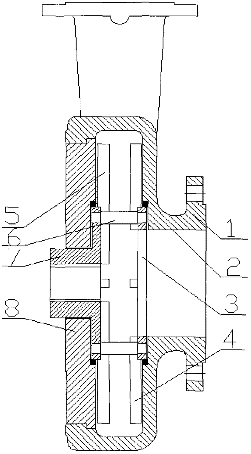
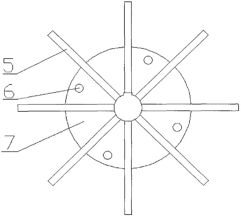
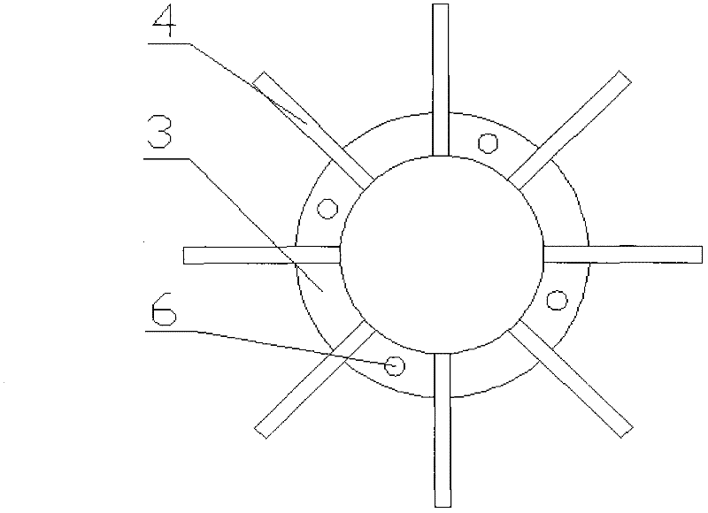
[0017] refer to figure 1 , This example includes the pump casing 1, the mouth ring 2, the driven ring 3, the driven vane 4, the driving vane 5, the connecting arm 6, the driving disc 7 and the rear pump cover 8. The drive disc rotates at high speed driven by the drive shaft, the connection between the drive disc 7 and the driven ring 3 is realized through the connection arm 6 to drive the driven ring 3 to rotate together, and the driven blade 4 is consolidated with the driven ring 3, the active vane 5 is fixed on the drive disc 7. The driving disc 7 is in clearance fit with the mouth ring on the rear pump cover 8 , and the driven ring 3 is in clearance fit with the mouth ring 2 on the pump casing 1 . The height of the driving vane 4 and the driven vane 5 is recommended to be less than 1 / 4 of the width of the pump chamber, and the distance between the ...


PUM


Abstract

An open discontinuous vane pump comprises an impeller with open discontinuous vanes, an inlet port ring, a drive port ring, a pump casing and the like. The impeller of the open discontinuous blade, its impeller saves the front and rear cover plates, its blade is discontinuous, divided into driving blade and driven blade, the blade form can be radial straight blade form, arc curved blade form or It is in the form of double inclined blades. The driving blades are fixed on the driving disk, and the driven blades are fixed on the driven ring. The driving disc is driven by the drive shaft to rotate at high speed, the minimum outer diameter of the driving disc is larger than the inner diameter of the pump inlet, and the largest outer diameter is smaller than the outer diameter of the blade; the inner diameter of the driven ring is equal to the inner diameter of the pump inlet, and the outer diameter is equal to the outer diameter of the driving disc. The driving disc and the driven ring are connected by connecting arms; the driving disc is matched with the driving port ring installed on the rear pump cover, and the driven ring is matched with the inlet port ring installed on the pump casing. The impeller of the present invention saves the front and rear cover plates of the impeller and some blade materials, which can reduce the deflection of the shaft and the bearing load, ensure the service life and save materials; and the open discontinuous blade impeller reduces the disc loss, and the solid phase particles are mainly concentrated In the vaneless area of ​​the impeller, the open blades can reduce the pressure of the shaft seal cavity and prevent crystal particles from entering the shaft seal cavity. At the same time, the driving disc and the driven ring are matched with the pump casing to reduce volume loss, improve pump efficiency, and reduce pump pressure. impeller cost.

Description

technical field [0001] The invention relates to an impeller, the main part of a pump, in particular to an open-type discontinuous vane pump impeller. Background technique [0002] In the prior art, the closed impeller is widely used as the rotating work part of the water pump. The structure of the closed impeller is that the front and rear cover plates sandwich the blades in the middle. When the fluid medium containing particles is transported, the partial blockage of the flow channel will affect the flow of the liquid. Normal flow; In addition, most of the existing open impeller blades are continuous. When transporting crystal particles, the particles will inevitably collide with the blades, resulting in increased wear of the blades, which will seriously affect the stability and life of the pump. Contents of the invention [0003] The purpose of the present invention is to provide a kind of open-type non-conductive pump with wide high-efficiency area, high head, good anti...

Claims


Application Information

Patent Timeline
Patent Type & Authority Applications(China)
IPC IPC(8): F04D1/00F04D29/22F04D29/24
Inventor 陈国明尹树孟周昌静徐长航高本金
Owner CHINA UNIV OF PETROLEUM (EAST CHINA)
Learn More