steering shaft

A technology of steering transmission shaft and shaft, applied in the direction of rotating motion shaft, etc., can solve the problems of transmission and inability to realize torque, and achieve the effect of simple structure

Inactive Publication Date: 2011-12-28
郭保可
View PDF5 Cites 2 Cited by
  • Summary
  • Abstract
  • Description
  • Claims
  • Application Information

AI Technical Summary

Problems solved by technology

However, when the angle between the input shaft and the output shaft is 90 degrees or even exceeds 90

Method used


Image

  • steering shaft
  • steering shaft
  • steering shaft

Examples


Embodiment Construction

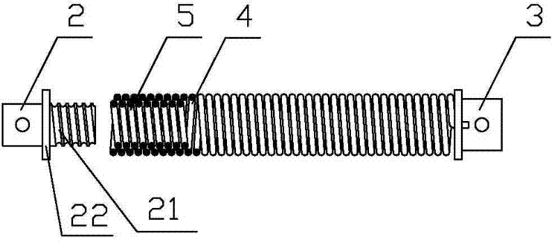
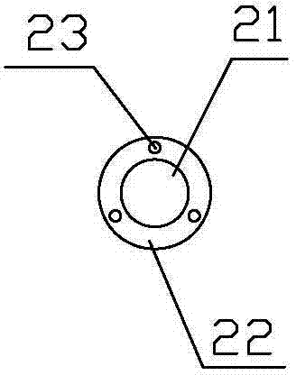
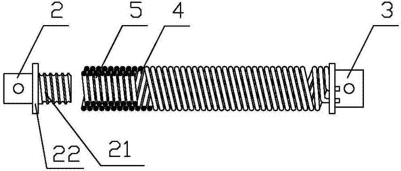
[0012] As shown in the figure, the steering transmission shaft according to the present invention includes a shaft and connecting pieces 2 and 3 connected to both ends of the shaft. The structure of the connecting pieces 2 and 3 can be adopted as required figure 2 The shown cylinder may also adopt a columnar structure such as a quadrangular prism, a pentagonal prism, or a hexagonal prism. The shaft includes an outer rod 4 and an inner rod 5, the outer rod 4 and the inner rod 5 are coil springs, the inner rod 5 is coaxially inserted in the inner cavity of the outer rod 4, in order to achieve a better use effect, The outer diameter of the inner rod 5 should be the same as or close to the inner diameter of the outer rod 4 . The helical directions of the inner rod 5 and the outer rod 4 are opposite, that is, one of them is a left-handed spring, and the other is a right-handed spring. The inner rod 5 and the outer rod 4 can adopt a monofilament spring, that is, a spring wound by ...


PUM


Abstract

The invention relates to a transmission mechanism in the mechanical field, in particular to a steering transmission shaft. It includes a shaft and connecting pieces connected to both ends of the shaft, and is characterized in that: the shaft includes an outer rod and an inner rod, both of which are coil springs, and the inner rod is coaxially inserted into the inner rod of the outer rod. In the cavity, the helical direction of the inner rod is opposite to that of the outer rod. The steering transmission shaft has a simple structure and can be used in various occasions of steering torque transmission, especially solves the problem of vertical steering transmission of torque that cannot be realized in the prior art, and can be used for torque transmission of large steering angles.

Description

technical field [0001] The invention relates to a transmission mechanism in the mechanical field, in particular to a steering transmission shaft. Background technique [0002] Transmission shafts are often used in various mechanical equipment to transmit torque. Ordinary transmission shafts can only achieve coaxial transmission, that is, when the torque of the input shaft is transmitted to the output shaft, the output shaft and the input shaft are required to be set coaxially. However, in actual work, there are often various angles between the input shaft and the output shaft of various transmission mechanisms, that is to say, when the input shaft is transmitted to the output shaft, it has a certain angle of steering. , Usually connected by a universal joint, the existing universal joint can provide a small steering angle, allowing the input shaft and the output shaft to be used when the angle between the input shaft and the output shaft does not exceed 90 degrees. However...

Claims


Application Information

Patent Timeline
IPC IPC(8): F16C1/02
Inventor 郭志振郭保可
Owner 郭保可
Why Eureka
Try Eureka