Eureka AIR delivers breakthrough ideas for toughest innovation challenges, trusted by R&D personnel around the world.

Dry and wet cycle climate hypergravity simulation system

A technology that simulates systems and dry-wet cycles, and is applied in weather resistance/light resistance/corrosion resistance, measuring devices, instruments, etc.

Active Publication Date: 2011-12-28
ZHEJIANG UNIV
View PDF4 Cites 32 Cited by
  • Summary
  • Abstract
  • Description
  • Claims
  • Application Information

AI Technical Summary

Problems solved by technology

[0006] The purpose of the present invention is to provide a dry-wet cycle climate hypergravity simulation system integrating rainfall and drying control to solve the problem of effectively simulating the dry-wet cycle climate in the supergravity centrifugal model

Method used


Image

  • Dry and wet cycle climate hypergravity simulation system
  • Dry and wet cycle climate hypergravity simulation system
  • Dry and wet cycle climate hypergravity simulation system

Examples


Embodiment Construction

[0025] The dry and wet cycle climate supergravity simulation system of the present invention is used in a supergravity centrifuge.

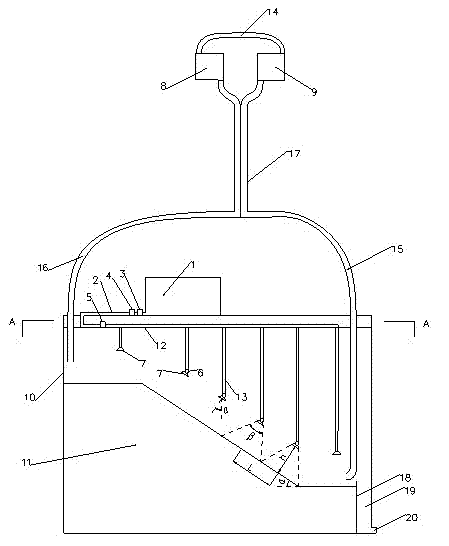
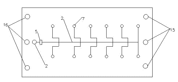
[0026] Such as figure 1 As shown, the dry-wet cycle climate supergravity simulation system of the present invention includes a supergravity centrifuge airborne model box 10, and an air heating dehumidifier 8, a blower 9 and a water tank 1 are provided outside the model box 10. The air outlet of the air heating dehumidifier 8 and the air inlet of the blower 9 are connected by an air guide tube 14, the air outlet of the blower 9 is connected with an air inlet tube 15, and the air inlet of the air heating dehumidifier 8 is connected with an air outlet tube 16. Both the air inlet pipe 15 and the air outlet pipe 16 extend into the interior of the model box 10.

[0027] The water tank 10 is fixed on the top of the exterior of the model box 10. The water tank 10 is made of metal with greater strength, so as to ensure that no major deformation or even damage...


PUM


Abstract

The invention discloses a dry-wet circulation climate hypergravity simulation system. According to the present invention, an air heating dehumidifier, an air blower and a water tank are arranged in the external of a hypergravity centrifuge-carried model box; a gas outlet of the air heating dehumidifier is connected with a gas inlet of the air blower through gas guiding pipes; a gas outlet of the air blower is connected with a gas inlet pipe; a gas inlet of the air heating dehumidifier is connected with a gas outlet pipe; the water tank is fixed on the top of the model box; the gas inlet pipe and the gas outlet pipe both extend to the internal of the model box; a rock-soil mass model is arranged on the bottom of the internal of the model box; an earthwork separator is arranged between the rock-soil mass model and a side wall of the model box, and the left space between the earthwork separator and the side wall of the model box is provided for a water collecting area; a water outlet is arranged on the bottom of the water collecting area; quadrate rain-fog nozzles are arranged above the rock-soil mass model, wherein the quadrate rain-fog nozzles are distributed in matrix; each quadrate rain-fog nozzle is communicated with the water tank through water transporting pipes; pressure sensors, pressure reducing valves and rain controlling switches are arranged on the water transportingpipes; the pressure sensors and the pressure reducing valves are arranged outside the model box.

Description

technical field [0001] The invention relates to a dry-wet cycle climate simulation system (including rainy season and dry season), in particular to a dry-wet cycle climate simulation system based on an airborne model box of a supergravity centrifuge. Background technique [0002] Climate change affects the service environment of geotechnical structures, and it is very easy to induce catastrophes such as excessive deformation and even instability of rock and soil mass. For example, heavy rainfall caused landslides and mudslides, which caused a large number of casualties and huge economic losses. The tragic experience of the Zhouqu mudslide disaster in 2010 is still fresh in my memory; the dry-wet cycle climate can induce permafrost melting and cause embankment deformation and instability. It is especially prominent in the Qinghai-Tibet Railway. [0003] In previous studies, field tests and indoor constant gravity small-scale model tests were mostly used. However, large-s...

Claims


Application Information

Patent Timeline
Patent Type & Authority Applications(China)
IPC IPC(8): G01N17/00
Inventor 陈云敏朱斌杨春宝孔令刚
Owner ZHEJIANG UNIV
Why Eureka
Eureka Blog
Learn More