
A Simulation Method of Injection Wave Interaction in Traveling Wave Tube

A technology of injection wave interaction and simulation method, which is applied in the field of simulation of injection wave interaction in traveling wave tubes

Inactive Publication Date: 2011-12-28
UNIV OF ELECTRONIC SCI & TECH OF CHINA
View PDF1 Cites 10 Cited by
  • Summary
  • Abstract
  • Description
  • Claims
  • Application Information

AI Technical Summary

Problems solved by technology

[0004] The purpose of the present invention is to solve the problems existing in the existing semi-analytical and semi-numerical parameter theoretical models for simulating the injection-wave interaction process of various traveling wave tubes, and propose a simulation method for the injection-wave interaction of traveling wave tubes

Method used


Image

  • A Simulation Method of Injection Wave Interaction in Traveling Wave Tube
  • A Simulation Method of Injection Wave Interaction in Traveling Wave Tube
  • A Simulation Method of Injection Wave Interaction in Traveling Wave Tube

Examples


Embodiment Construction

[0015] The present invention will be further described below in conjunction with the accompanying drawings and specific embodiments.

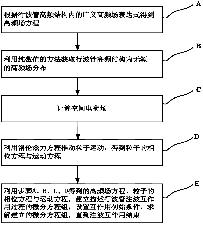
[0016] The flow chart of the simulation method of injection wave interaction of traveling wave tube of the present invention is as follows figure 1 shown, including the following steps:

[0017] A. Obtain the high-frequency field equation according to the generalized high-frequency field expression of the high-frequency structure of the traveling wave tube.

[0018] In the high-frequency structure of traveling wave tube with axial periodicity, the generalized high-frequency electromagnetic field can be expressed as formula (1.1)

[0019] E rf ( x ⊥ , z , t ) ...


PUM


Abstract

The invention belongs to a traveling wave tube simulation technology and discloses a method for simulating the dominant wave interaction of traveling wave tubes. Specific to the problems existing in the process of simulating the dominant wave interaction of various traveling wave tubes with the conventional semi-analytical and semi-numerical parameter theoretical model, high-frequency field distributions in high-frequency structures of traveling wave tubes are obtained with a pure numerical method in the method, and simultaneous differential equations are established by combining a high-frequency field equation, a particle phase equation and a motion equation, so that a dominant wave interaction parameter theoretical model suitable for various traveling wave tubes is established. The method can be used for simulating the dominant wave interaction processes in various traveling wave tubes, has high efficiency of the parameter theoretical model, and can be applied to numerical simulation of the interactions of electron beams and high-frequency fields in various traveling wave tubes with periodic high-frequency structures.

Description

technical field [0001] The invention belongs to the simulation technology of traveling wave tubes, in particular to a simulation method for injection wave interaction of traveling wave tubes. Background technique [0002] Traveling wave tube is one of the most widely used vacuum electronic devices, widely used in satellite communication, radar, electronic countermeasures and other fields. At present, the use of computer aided design (Computer Aided Design, CAD) technology is one of the main means to save costs, improve design and improve the overall performance of traveling wave tubes. In the CAD technology of traveling wave tubes, it is of great significance to analyze the interaction between electron beam and high-frequency electromagnetic field in traveling wave tube (namely beam interaction). The injection wave interaction in the TWT is a self-consistent process: the high-frequency electromagnetic field in the high-frequency structure of the TWT and the space charge fie...

Claims


Application Information

Patent Timeline
IPC IPC(8): G06F17/50
Inventor 胡玉禄彭维峰李斌李建清杨中海朱小芳
Owner UNIV OF ELECTRONIC SCI & TECH OF CHINA
Features
  • Generate Ideas
  • Intellectual Property
  • Life Sciences
  • Materials
  • Tech Scout
  • Unparalleled Data Quality
  • Higher Quality Content
  • 60% Fewer Hallucinations
Learn More