Mechanical trimming device and trimming method

A mechanical trimming and mechanical technology, applied in the direction of valve devices, mechanical equipment, valve operation/release devices, etc., can solve the problems of space requirement, low thread surface roughness, expensive, etc., and achieve the effect of reducing the impact

Inactive Publication Date: 2015-08-19
SHENZHEN MINDRAY BIO MEDICAL ELECTRONICS CO LTD
View PDF6 Cites 0 Cited by
  • Summary
  • Abstract
  • Description
  • Claims
  • Application Information

AI Technical Summary

Problems solved by technology

US Patent 1,532,702 describes this method; however, the disadvantage of this method is that it is relatively expensive, requires low thread surface roughness, and requires space

Method used


Image

  • Mechanical trimming device and trimming method
  • Mechanical trimming device and trimming method
  • Mechanical trimming device and trimming method

Examples


other Embodiment approach

[0042] Other embodiments may also include situations where very small length adjustments are required, eg other types of actuator units.

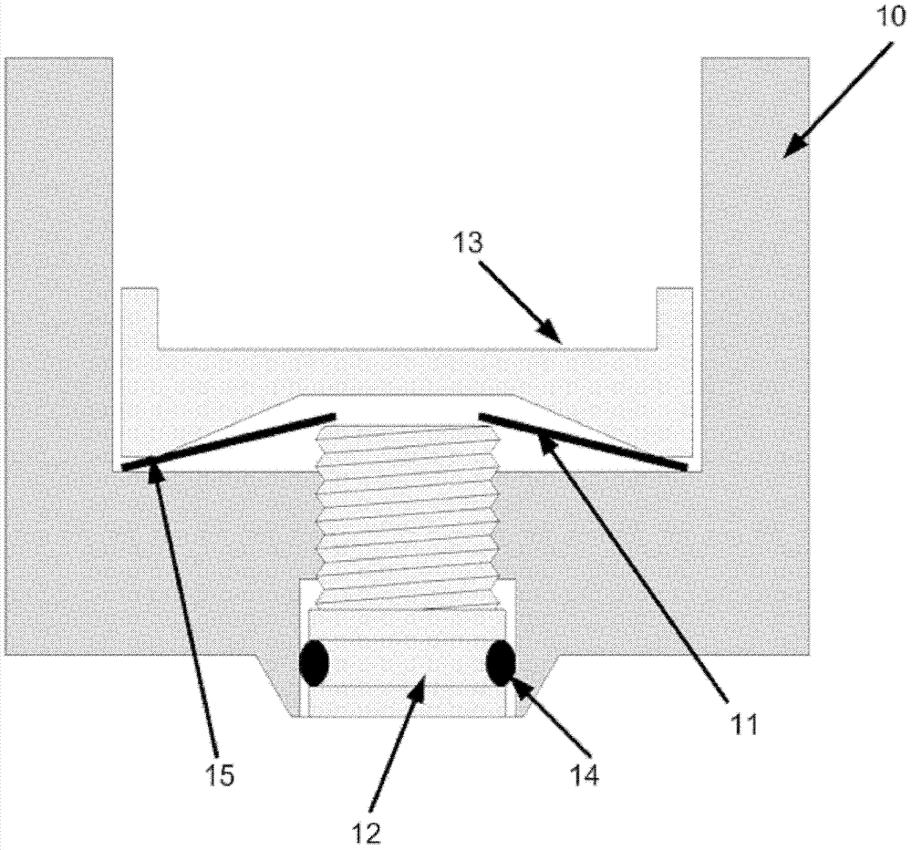
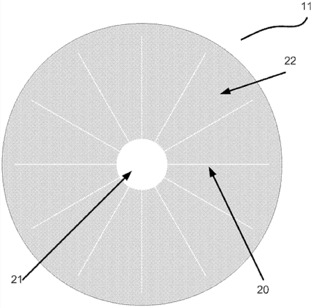
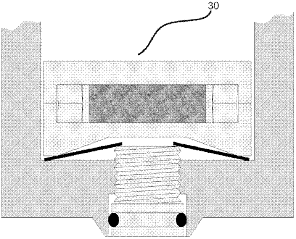
[0043] In another aspect, the present invention also provides a method for dressing in a direction normal to the surface of a mechanical dressing device, the method comprising adjusting a screw to lift the center of the disc-like member so that the disc-like member operates as a lever , the lever includes a first distribution contact point and a second distribution contact point, the first distribution contact point is in contact with the edge of the cavity of the second body, and the second distribution contact point is in the cavity of the disc-shaped member The outer edge of the cavity is in contact with the surface of the first body, the first body is a movable body, and the second body moves relative to the first body. Further, the method uses the above-mentioned mechanical trimming device to mechanically trim the stroke of the piezoel...


PUM


Abstract

The invention relates to a device for trimming the thickness of a mechanical body. Wherein, the trimming is realized in the following manner: a screw is screwed through the threaded hole, one end of the screw presses the center of the disc-shaped part, and the disc-shaped part is deformed to act as a lever to act on the adjacent body. This will reduce the influence of the screw lead on the transmission determined by this lever.

Description

technical field [0001] The present invention relates to a device for compensating for mechanical tolerances using trimming in tolerance critical designs. Background technique [0002] When designing mechanical systems, their construction often uses components of different materials. The reason may be the special requirements of the parts used, such as hardness, loss, corrosion resistance, surface roughness, transparency, color, electrical characteristics, melting point, cost, etc. [0003] When combining different materials, the components used often have different mechanical tolerances. These tolerances include dimensional tolerances or stiffness tolerances of the components used. [0004] Spring stiffness tolerances are often quite large, which is why springs used in mechanical systems require mechanical dimensional tolerances for specific forces. [0005] In many cases, tolerances are improved by mechanical adjustment. However, this is not always possible if the compo...

Claims


Application Information

Patent Timeline
Patent Type & Authority Patents(China)
IPC IPC(8): G12B5/00G12B7/00
CPCF16K31/004H10N30/88
Inventor 戈兰·西维斯
Owner SHENZHEN MINDRAY BIO MEDICAL ELECTRONICS CO LTD
Why Eureka
Try Eureka