
Led lamp, lamp base and method of operating the led lamp

A technology for lamp holders and illuminants, which can be used in the use of semiconductor lamps, lighting and heating equipment, components of lighting devices, etc., and can solve problems such as insufficiently illuminated spaces

Inactive Publication Date: 2011-12-28
OSRAM GMBH
View PDF3 Cites 5 Cited by
  • Summary
  • Abstract
  • Description
  • Claims
  • Application Information

AI Technical Summary

Problems solved by technology

In a ceiling light, it is usually vertically downwards, thus not adequately illuminating the walls of the space

Method used


Image

  • Led lamp, lamp base and method of operating the led lamp
  • Led lamp, lamp base and method of operating the led lamp
  • Led lamp, lamp base and method of operating the led lamp

Examples


Embodiment Construction

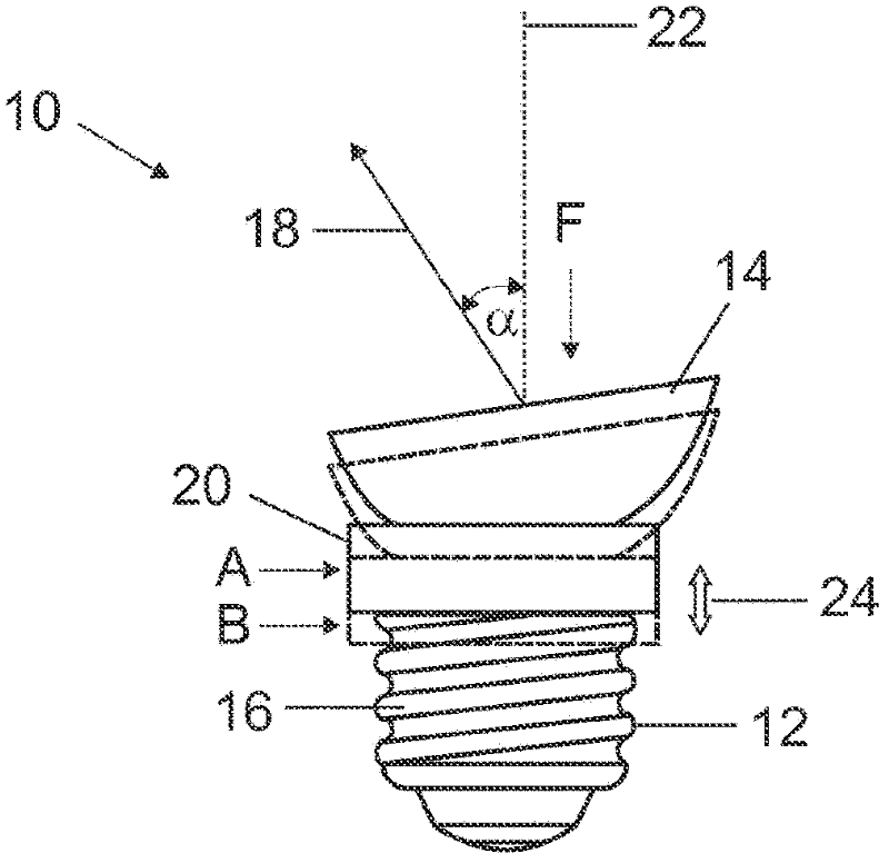
[0038] exist figure 1 The lamp 10 shown in has a helical base 12 to which a reflector 14 is connected. exist figure 1 Only the thread 16 of the base 12 is shown in FIG. In the reflector 14, a plurality of light emitting diodes (LEDs) are arranged on a circuit board, wherein all the light emitting diodes are oriented in one direction. exist figure 1 You cannot see the circuit board with the LEDs in it. The light emitting diodes are all pointing in direction 18 according to their orientation in reflector 14 . The intensity distribution of the emitted light, which is measured at a constant distance around lamp 10 , has a rotationally symmetrical structure about a predetermined axis through direction 18 . In other words, the light emitting cone of the lamp 10 has the shape of a mathematical cone. The maximum strength is here achieved in direction 18 , that is to say the axis of symmetry of the vertebral body.

[0039] The reflector 14 with the light-emitting diodes arranged...


PUM


Abstract

A lamp may include illumination means which include at least one LED, and having a base, by way of which the lamp can be connected to a mounting in order to be supplied with voltage, wherein the illumination means are connected to the base by way of a mechanism which in a first state couples the illumination means in rotatable fashion to the base around an axis and in a second state couples the illumination means to the base in a rotatably fixed manner, and light emitted by the illumination means has an intensity distribution which is asymmetric with respect to the axis.

Description

technical field [0001] The invention relates to an LED lamp (LED—light-emitting diode) according to the preamble of claim 1 as well as to a lampholder for the lamp and a method for operating the LED lamp. Background technique [0002] LED lamps have the great economic advantage that they require only a fraction of the electrical energy compared to conventional light bulbs or compact fluorescent lamps in order to produce light of the same brightness as conventional incandescent lamps. Of course, the luminous characteristics of LEDs are limited by technical structural constraints. In other words, the light emitted by the LED lamp is concentrated relatively strongly into a beam. Typically, LED lamps emit light in the form of a conical beam of light. The light therefore has sufficient intensity for illumination only in small spatial angles. Another name for this type of light is spotlight. In order to increase the beam angle, there are also LED lamps that achieve a beam angl...

Claims


Application Information

Patent Timeline
Patent Type & Authority Applications(China)
IPC IPC(8): F21V14/02F21K99/00
CPCF21V14/02F21V19/02F21K9/135F21Y2101/02Y02B20/386F21V19/006F21K9/58F21K9/232F21K9/65F21Y2115/10
Inventor 哈拉尔德·德利安马库斯·霍夫曼
Owner OSRAM GMBH
Learn More